

Miniature transmission mechanism
A transmission mechanism and miniature technology, which is applied in the direction of transmission, gear transmission, mechanical equipment, etc., can solve the problems of insufficient power output and complex structure, and achieve the effect of simple and optimized structure, small size and large power output
- Summary
- Abstract
- Description
- Claims
- Application Information
AI Technical Summary
Problems solved by technology
Method used
Image

Examples
Embodiment 1
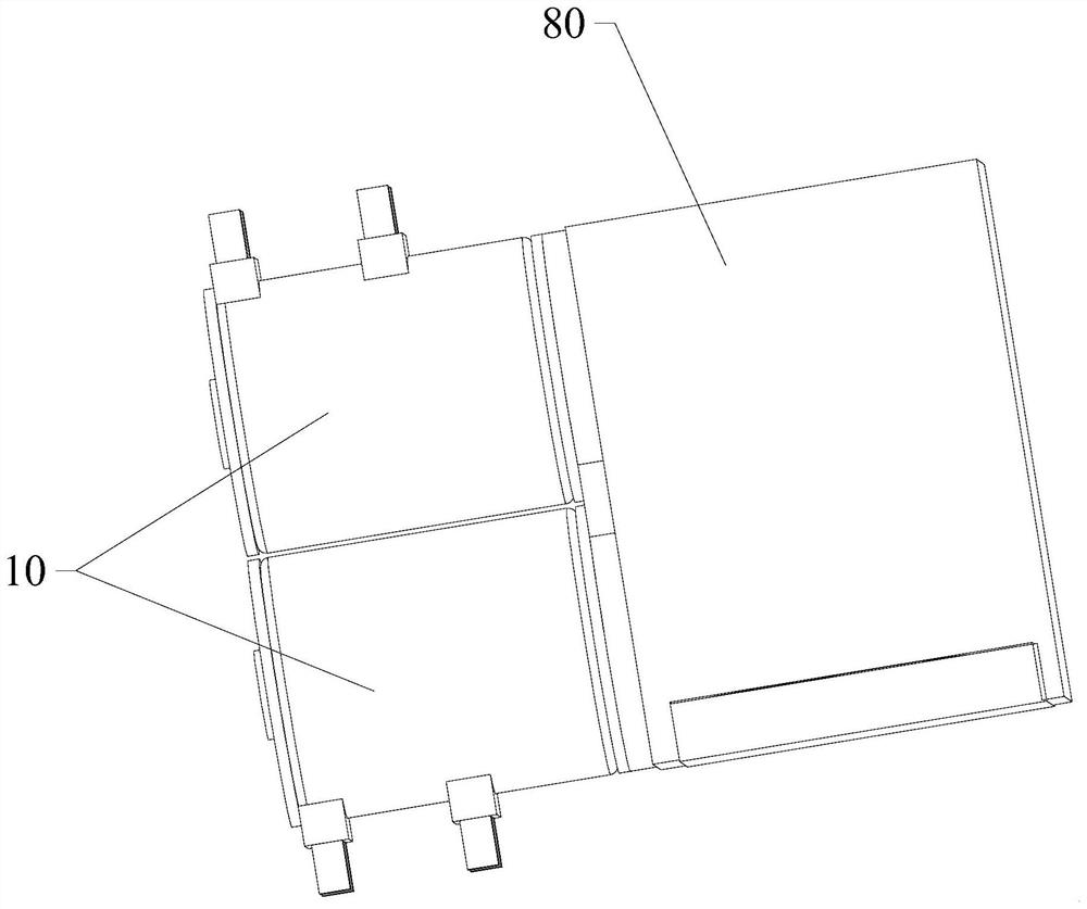
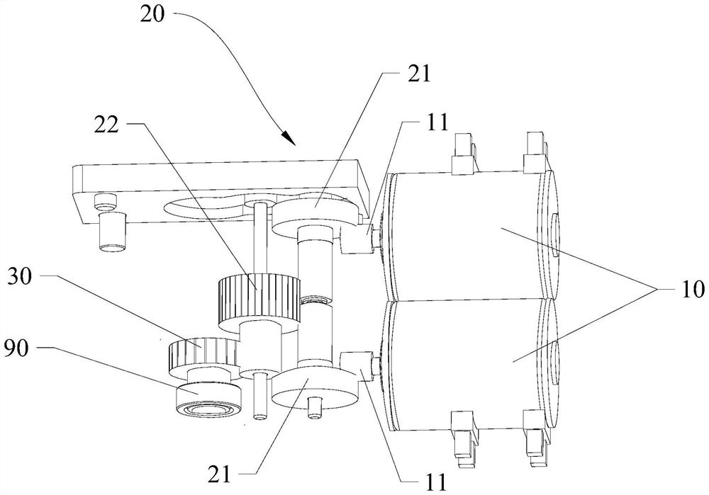
[0032] Please also refer to figure 1 and figure 2 , the micro transmission mechanism provided by Embodiment 1 of the present application will now be described. The micro transmission mechanism includes two driving parts 10 , a transmission assembly 20 and an output part 30 . The transmission assembly 20 is connected between the driving member 10 and the output member 30 , so that the power of the two driving members 10 passes through the transmission assembly 20 and is transmitted to the output member 30 for output.
[0033] Further, the driving shafts of the two driving parts 10 are provided with driving gears 11 , and the two driving parts 10 are connected with the transmission assembly 20 through the driving gears 11 . Specifically, the transmission assembly 20 is a gear transmission assembly and includes a first transmission assembly 21 , the first transmission assembly 21 is a steering gear, for example, the first transmission assembly 21 is a face gear. The two first...
Embodiment 2
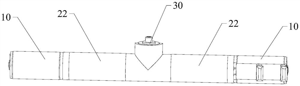
[0043] Please also refer to image 3 and Figure 4 , the micro transmission mechanism provided by Embodiment 2 of the present application will now be described. The micro transmission mechanism includes two driving parts 10 , a transmission assembly 20 , an output part 30 and a bearing 90 . Wherein the structure and matching mode of the bearing 90 are consistent with the foregoing embodiments, so image 3 and Figure 4 Bearing 90 is omitted.
[0044] The transmission assembly 20 is a gear transmission assembly and includes two first transmission assemblies 21, and the first transmission assembly 21 is a steering wheel, specifically a bevel gear. The two driving members 10 drive the two first transmission assemblies 21 to rotate in a one-to-one correspondence. The output member 30 is an output gear, specifically a bevel gear. The output member 30 is located between the two first transmission assemblies 21 , and the two first transmission assemblies 21 are both engaged wit...
Embodiment 3
[0052] Please also refer to Figure 5 and Figure 6 , the micro transmission mechanism provided by Embodiment 3 of the present application will now be described. The micro transmission mechanism includes two driving parts 10 , a transmission assembly 20 , an output part 30 and a bearing 90 . The structure and matching method of the bearing 90 are consistent with the foregoing embodiments.
[0053] The two driving elements 10 are respectively located on opposite sides of the output element 30 . The transmission assembly 20 is a gear transmission assembly and includes two first transmission assemblies 21, and the first transmission assembly 21 is a steering wheel, specifically a face gear. The two driving members 10 directly or indirectly drive the two first transmission assemblies 21 to rotate in one-to-one correspondence. The output member 30 is an output gear and is located between the two first transmission assemblies 21 , and the two first transmission assemblies 21 are...
PUM
 Abstract
Description
Claims
Application Information