Wheel house panel mounting structure

A technology for installing structures and cover plates, which is applied to superstructures, subassemblies of superstructures, transportation and packaging, etc. It can solve problems such as insufficient operating space, prolonged assembly time, and difficulties in installation and disassembly, so as to improve assembly efficiency and installation And disassembly is simple and convenient, saving labor costs

Inactive Publication Date: 2014-02-12
SHANGHAI SHUANGJIE TECH
View PDF8 Cites 0 Cited by
  • Summary
  • Abstract
  • Description
  • Claims
  • Application Information

AI Technical Summary

Problems solved by technology

[0006] In view of the above-mentioned problems, the present invention discloses a wheel cover plate installation structure to overcome the problem of using screw connection in the prior art, and due to structural and other reasons, the operation space is not enough during installation, resulting in difficulty in installation and disassembly, or the prolongation of assembly time

Method used


Image

  • Wheel house panel mounting structure
  • Wheel house panel mounting structure
  • Wheel house panel mounting structure

Examples


Embodiment 1

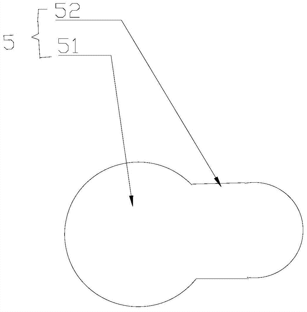
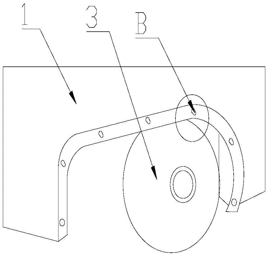
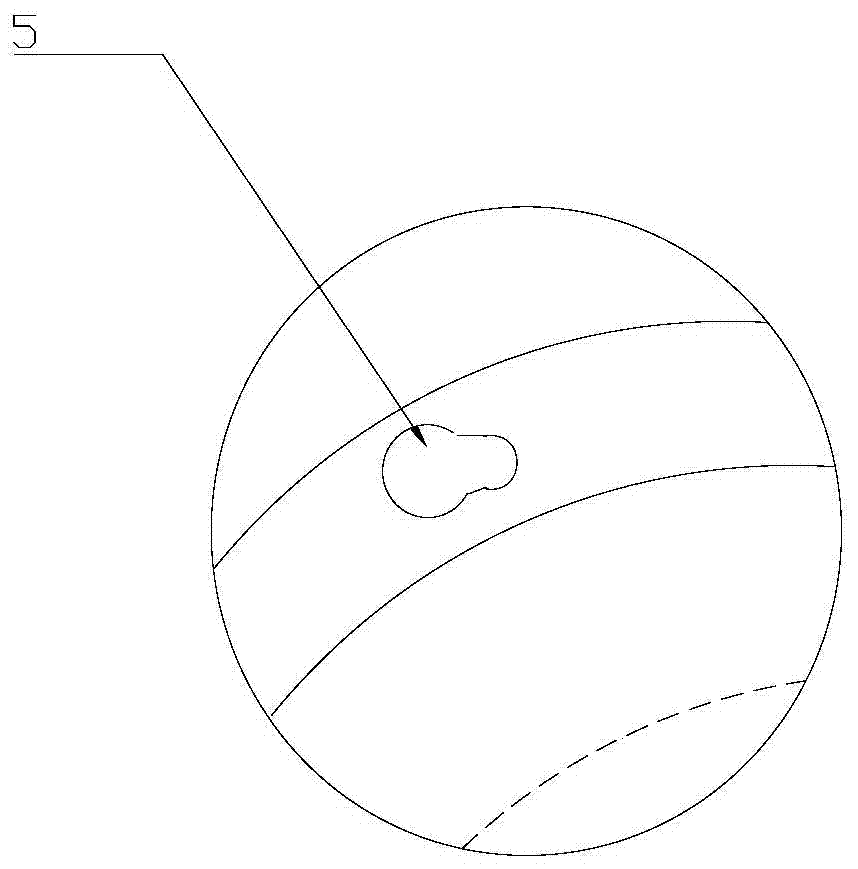
[0028] Such as Figure 1 to Figure 7 As shown, the installation structure of the wheel cover plate includes the wheel cover plate 2. The wheel cover plate 2 is installed on the wheel wing plate 1 of the car shell to protect the wheels 3. The wheel cover plate 2 is provided with five mounting buckle assemblies 6 and the mounting hole 7, the mounting buckle assembly 6 is composed of a mounting cap 62 and a mounting buckle 61, the mounting buckle 61 is connected in turn by the first cylinder 611, the second cylinder 612 and the third cylinder 613 from thick to thin, and the wheel wing The installation buckle fitting hole 5 on the board 1 includes a fitting portion 51 and a locking portion 52 connected thereto. The fitting portion 51 and the locking portion 52 are circular hole structures, and the diameter of the fitting hole 51 is larger than that of the locking portion 52 , the third cylinder 613 passes through the mounting hole 7 from one side of the wheel house plate 2, the mo...

Embodiment 2

[0033] Such as Figure 1 to Figure 3 , Figure 8 and Figure 9 As shown, this embodiment is roughly the same as Embodiment 1, and the difference is that in Embodiment 1, the mounting buckle assembly 6 is composed of a mounting cap 62 and a mounting buckle 61, and the mounting buckle 61 is composed of a first cylinder 611, a second The cylinder 612 and the third cylinder 613 are connected sequentially from thick to thin, and the mounting buckle assembly can be a plastic mounting buckle assembly. In this embodiment, the mounting buckle assembly 6 is two-layer stepped, made of metal, and connected to the wheel house plate 2 by welding.

[0034] In the present invention, the mounting buckle fitting holes connected with the mounting buckle assembly and the matching portion and the locking portion are adopted. When installing, only the mounting buckle assembly on the rear wheel cover plate and the mounting buckle fitting hole of the wheel wing plate need to be aligned. Then slide...


PUM


Abstract

The invention discloses a wheel house panel mounting structure which comprises a wheel house panel, wherein the wheel house panel is mounted on a wheel wing plate of a vehicle casing; a plurality of mounting buckle assemblies are arranged on the wheel house panel; mounting buckle matching holes corresponding to the mounting buckle assemblies are formed in the wheel wing plate; and the wheel house panel penetrates through the mounting buckle matching holes through the mounting buckle assemblies to be assembled together with the wheel wing plate. With the adoption of the wheel house panel mounting structure, problems of insufficient operating space during mounting and difficulty in mounting and dismounting because of structures and the like when screws are used for connection in the prior art can be solved, the mounting and the dismounting are simple and convenient, the assembling efficiency is improved, and the labor cost is saved.

Description

technical field [0001] The invention relates to the technical field of wheel cover plates, in particular to a wheel cover plate installation structure. Background technique [0002] In real life, the installation structure of the wheel cover plate used on the electric vehicle is connected by screws to ensure the limit and fixation of the wheel cover plate so that there will be no abnormal noise and looseness during the driving of the electric vehicle. Although the installation is reliable , but sometimes due to the structure and other reasons, the operating space during installation is not enough, resulting in difficulty in installation and disassembly, or prolonging the assembly time. [0003] Chinese patent (publication number: CN1229737A) discloses a wheel cover, including: a fixed side mounting member installed at the center of the vehicle wheel; a movable side mounting member rotatably mounted at the center of the fixed side mounting member; The disc-shaped wheel cover...

Claims


Application Information

Patent Timeline
IPC IPC(8): B62D25/16
Inventor 唐权
Owner SHANGHAI SHUANGJIE TECH
Why Eureka
Try Eureka