Geothermal heat-pumping system

A technology of ground source heat pumps and pipelines, applied in heat pumps, geothermal energy power generation, heating devices, etc., can solve problems such as difficulty in starting air-cooled (hot) water units, increase energy consumption of auxiliary electric heating, etc., and achieve significant environmental benefits and smooth operation Stable and reliable effect

Inactive Publication Date: 2006-11-01
上海大智科技发展有限公司
View PDF0 Cites 21 Cited by
  • Summary
  • Abstract
  • Description
  • Claims
  • Application Information

AI Technical Summary

Problems solved by technology

[0003] The purpose of the present invention is to provide a ground source heat pump system. The ground source heat pump system described in the prior art should solve the problems of the air-coo

Method used


Image

  • Geothermal heat-pumping system

Examples


Embodiment Construction

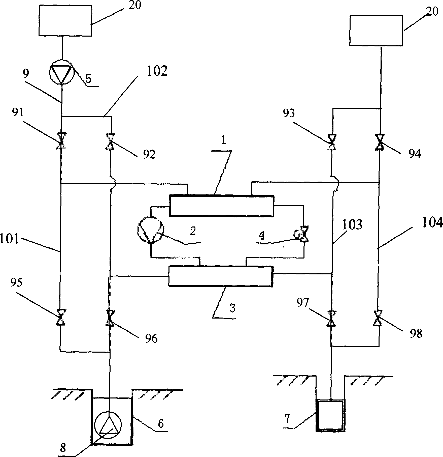
[0011] Such as figure 1 As shown, the ground source heat pump system of the present invention is composed of an evaporator 1, a condenser 3, a compressor 2 and an expansion valve 4. One end of the evaporator 1 is connected to one end of the compressor 2 through a refrigerant pipeline, and the compressor The other end of 2 is connected to one end of condenser 3 through a refrigerant pipeline, the other end of condenser 3 is connected to one end of expansion valve 4 through a refrigerant pipeline, and the other end of expansion valve 4 is connected to the other end of evaporator 1 through a refrigerant pipeline. One end is connected, the evaporator 1, the condenser 3 and the refrigerant pipeline are provided with refrigerant, wherein the evaporator 1 is provided with a first heat exchange pipeline, and one end of the first heat exchange pipeline is Connect the outlet of an indoor circulating water pipe 9, a first control valve 91 is arranged between the first heat exchange pipe ...


PUM


Abstract

A geothermal energy resources heat pump system consists of an evaporator, a condenser, a compressor and an expansion valve and they are connected one by one to form a heat-exchanging unit. The evaporator and the condenser are connected with the well-water pipeline separately via the valve set and the indoor circulating water pipeline. In the process of heating in winter and refrigerating in summer switching the valve set separately can make the indoor circulating water and the well water flow through the evaporator or the condenser separately according to the needs.

Description

technical field [0001] The invention relates to refrigeration and heating technology, in particular to ground source heat utilization equipment, in particular to a ground source heat pump system. Background technique [0002] In the prior art, the air-cooled (hot) water unit is used for heating or cooling of buildings, and the air-cooled (hot) water unit will have difficulty starting when the outdoor temperature is as low as -8°C, and it is necessary to increase the air-cooled heat pump. Auxiliary electric heating increases the energy consumption of the system. Contents of the invention [0003] The purpose of the present invention is to provide a ground source heat pump system. The ground source heat pump system described in the prior art should solve the problems of the air-cooled (hot) water unit in the prior art that it is difficult to start at low outdoor temperatures and the energy consumption of auxiliary electric heating needs to be increased. technical problem. ...

Claims


Application Information

Patent Timeline
IPC IPC(8): F25B30/06F24J3/08
CPCY02E10/10
Inventor 霍小平
Owner 上海大智科技发展有限公司
Why Eureka
Try Eureka