
Switch assembly

A technology of switch components and contact rods, which is applied in the direction of electric switches, electrical components, DC motor deceleration devices, etc., and can solve problems such as poor contact

Active Publication Date: 2006-11-01
SHANGHAI BAICHENG ELECTRONICS
View PDF3 Cites 9 Cited by
  • Summary
  • Abstract
  • Description
  • Claims
  • Application Information

AI Technical Summary

Problems solved by technology

[0006] An object of the present invention is to solve the problem of poor contact at the pivotal connection between the pivotal contact lever and the support in the conventional switch

Method used


Image

  • Switch assembly
  • Switch assembly
  • Switch assembly

Examples


Embodiment Construction

[0100] A switch assembly according to a preferred embodiment of the present invention, which is a high-power DC switch assembly, will be described in detail below with reference to the accompanying drawings. The invention can be used for ordinary switches, but the effect is more prominent when used for high-power DC switch components.

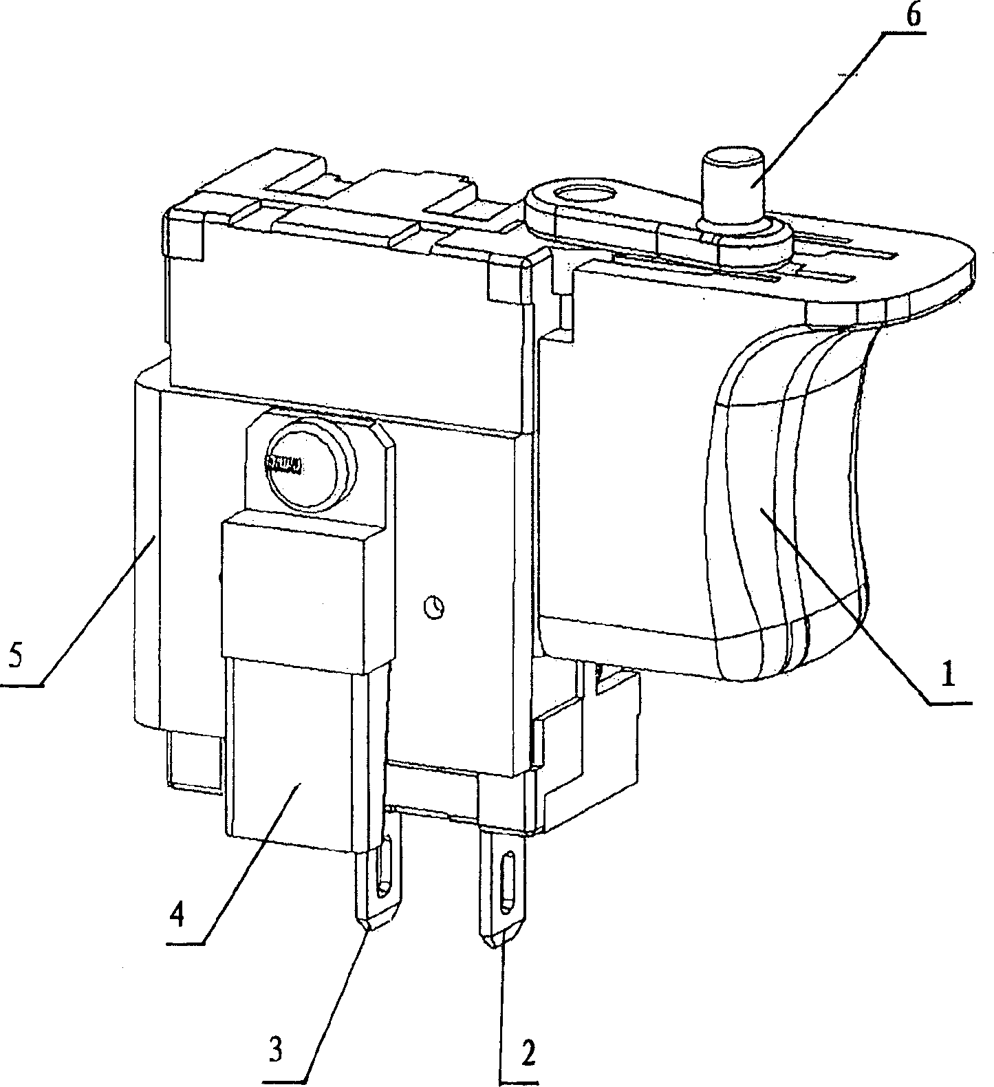
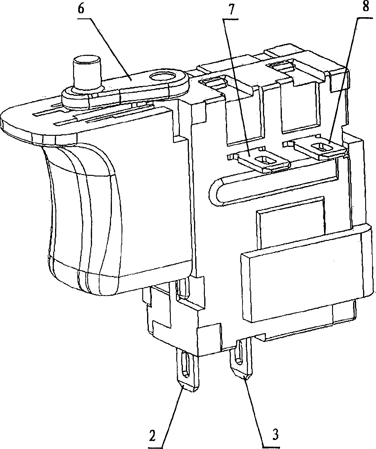
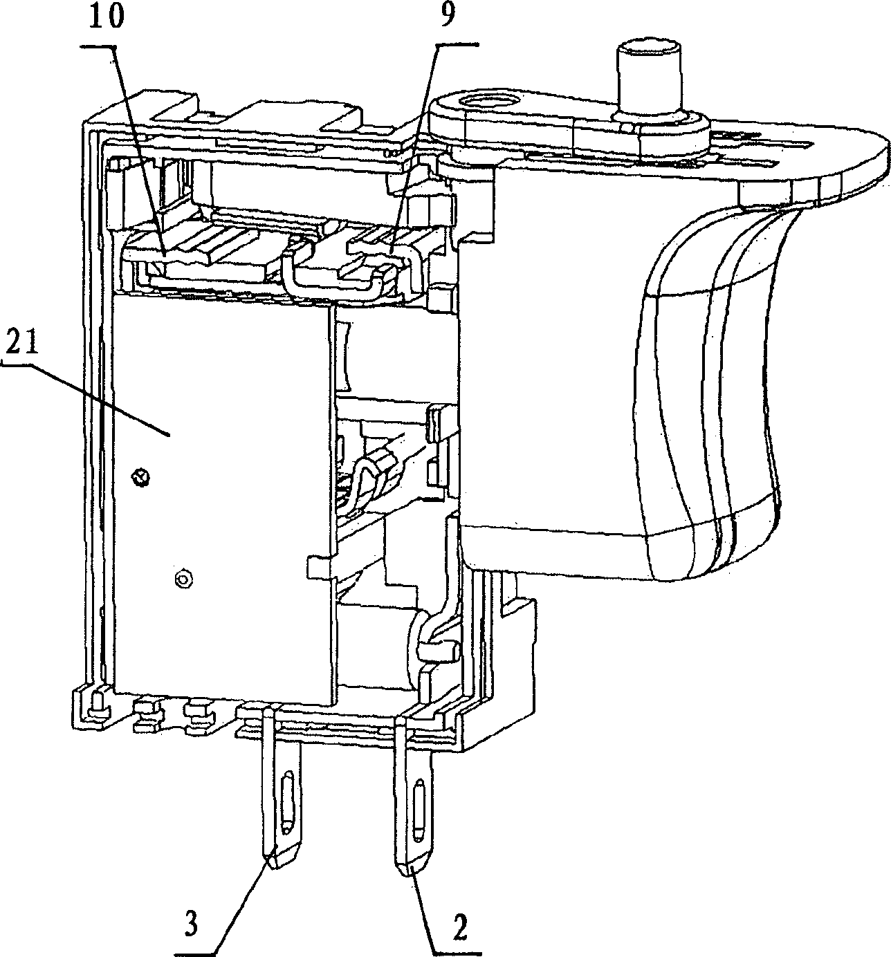
[0101] Such as figure 1 and 2 As shown, it can be seen from the outside that the switch assembly includes a housing, a trigger 1, a first input terminal 2 and a second input terminal 3 for respectively connecting with a voltage source such as a positive pole and a negative pole of a battery, and a terminal for connecting with a motor Connected first external output terminal 7 and second external output terminal 8 , MOS field effect transistor 4 as a solid state switch, heat sink 5 and forward / reverse conversion rod 6 . The operator can control the trigger. When the trigger 1 extends to its outermost position, the switch assembly is disconnec...


PUM


Abstract

The invention relates to a high power DC switch and solves the problem of loose contact between the pivoted contact lever and the pivoted joint of support unit. It minimizes the heat generated from the portion between the pivoted contact lever and the contact point by adding an attached contact plate parallel with the pivoted contact level, and further minimizes the heat from the joint between the internal output end of forward / backward transducer and the changeover contact plate by adding a bi-corrugated shape convex contact portion on the internal output end of the forward / backward transducer.

Description

technical field [0001] The present invention relates to an electrical switch, in particular to a high-power DC switch, and more particularly to a trigger switch for trigger control of power tools. Background technique [0002] A Marquardt (Trademark) type 2711.5507 high power DC switch is already known in the art with a power of 18V DC 25A. US6717080B1 discloses a trigger switch assembly for a power tool with an electric motor. US6741051B2 discloses a trigger controller for a power tool including an electric motor. US6104105 also discloses an electrical switch for turning on or off a tool with an electric motor. [0003] The switches mentioned above all use the pivoting contact rod mechanism to realize the connection and disconnection of the current. One end of the pivoting contact rod is pivotally connected to the support part, the support part is connected to the input end of the current, and the output end of the circuit A fixed contact is connected to the top, and the...

Claims


Application Information

Patent Timeline
IPC IPC(8): H01H3/42H01H13/52H01H13/64H02P1/22H02P3/08
CPCH01H1/5833H01H9/061H01H9/063H01H9/40H01H9/52H01H13/08H01H2001/0005
Inventor 徐新生
Owner SHANGHAI BAICHENG ELECTRONICS
Learn More