

Thyristor triggered control method and device for dynamic reactive compensation
A technology of trigger control and thyristor, applied in reactive power compensation, reactive power adjustment/elimination/compensation, etc., can solve problems such as lack of real-time performance, response speed limitation, etc., and achieve good application prospects
- Summary
- Abstract
- Description
- Claims
- Application Information
AI Technical Summary
Problems solved by technology
Method used
Image

Examples
Embodiment Construction
[0048] The present invention will be further described below in conjunction with the accompanying drawings and embodiments.
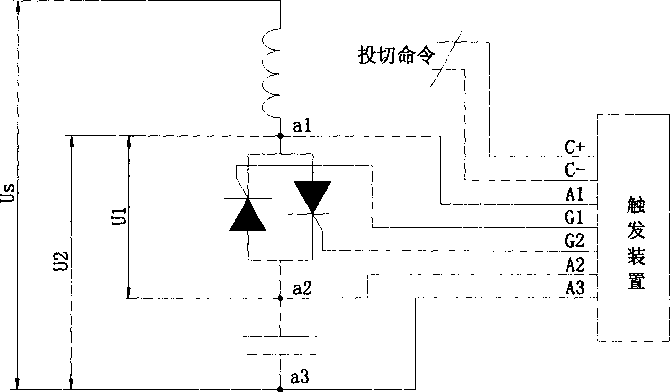
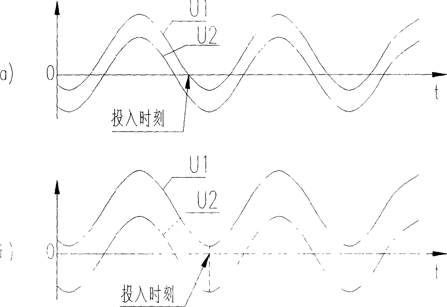
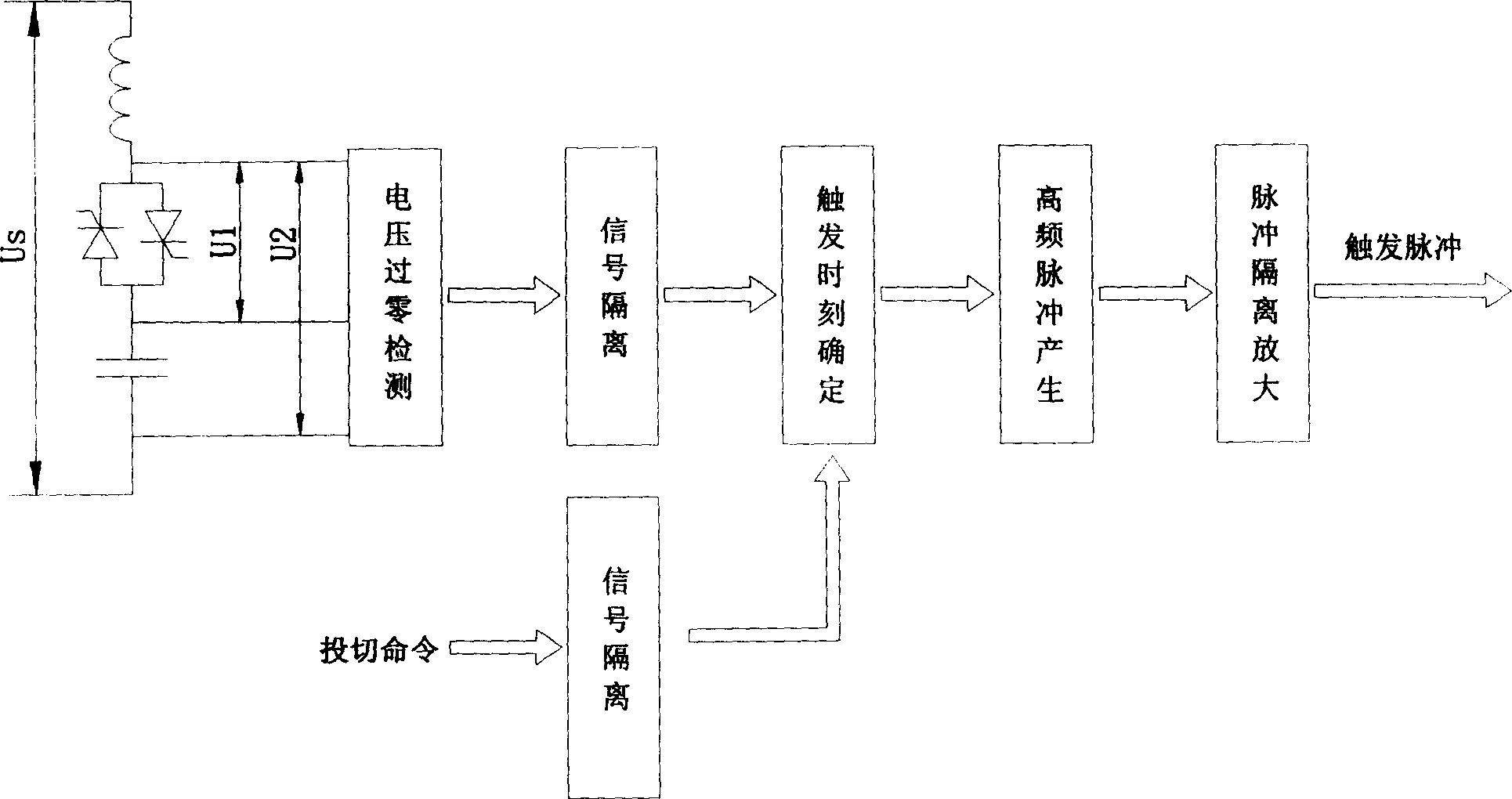
[0049] see Figure 1-Figure 3 , the thyristor trigger control method used for dynamic reactive power compensation timely collects the voltage U1 at both ends a1 and a2 of the thyristor connected in reverse parallel, collects the voltage U2 at both ends a1 and a3 of the thyristor connected in reverse parallel and the capacitor at both ends, and converts the voltage U1 and The voltage U2 is used as the basis for determining the input time of the entire capacitor branch; among them, the voltage U1 is the voltage across the thyristor, and the voltage U2 is the voltage sum of the thyristor and the capacitor;
[0050] When the thyristor is not conducting, the voltage U2 is equal to the system voltage U S , the voltage U1 is equal to the system voltage minus the capacitor residual voltage,
[0051] (1) When the capacitor residual voltage is less than the sys...
PUM
 Abstract
Description
Claims
Application Information