Resource distributing method while traditional optical transfer net and intelligent optical network grouping
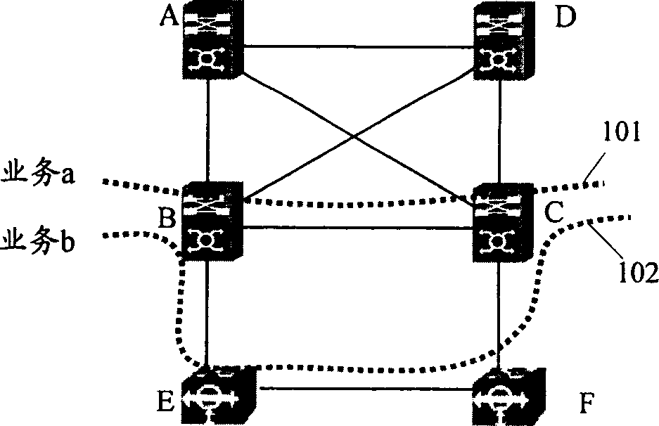
A technology of intelligent optical network and optical transport network, applied in the direction of transmission system, network interconnection, multiplexing system selection device, etc. Restoration, failure of business b102 protection or restoration etc.
- Summary
- Abstract
- Description
- Claims
- Application Information
AI Technical Summary
Problems solved by technology
Method used
Image
Examples
Embodiment 1
[0108] Embodiment 1: a method for configuring and using a virtual TE link for fault monitoring and participating in route calculation.
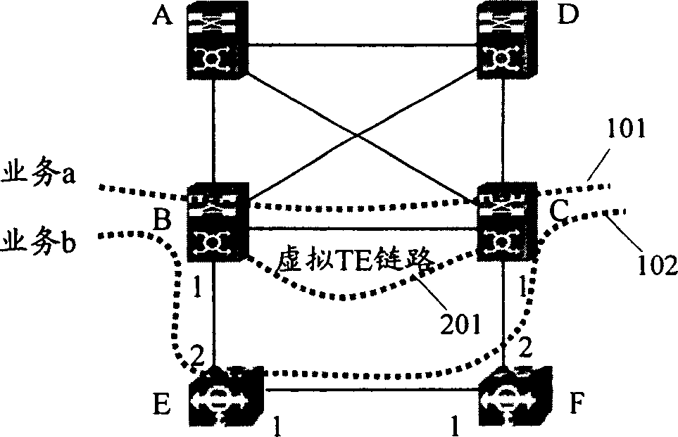
[0109] refer to image 3 , assuming that VC4 time slots 1 to 16 of the links between NE B and NE, NE E and F, and NE F and C are to be configured as bandwidth resources of a virtual TE link.
[0110] The method for configuring and using the virtual TE link described in this embodiment specifically includes the following steps:
[0111] 101. On network element B and network element C, respectively set VC4 time slots 1 to 16 on optical ports B.1 and C.1 as the reserved state, and establish optical ports E on network element E and network element F respectively .1 and E.2, and between F.1 and F.2 VC4 timeslots 1 to 16 for cross-connection;
[0112] 102. Configure optical port B.1 on network element B as a virtual TE link, and its bandwidth resources are VC4 time slots 1 to 16 of optical port B.1, and configure the remote network element of the...
Embodiment 2
[0122] Embodiment 2: When an MSP ring spanning the ASON and the traditional OTN is configured at the boundary between the traditional OTN and the ASON, configure and use a virtual TE link that only performs fault monitoring but does not participate in route calculation.
[0123] refer to image 3 , assuming that a 2-fiber bidirectional multiplex section ring is configured between network element B, network element E, network element F, and network element C, and only includes the above-mentioned multiplex section ring in ASON through optical port B.2-optical port The information in part C.2 does not include the part formed between network element B and network element C via network element E and network element F in the above-mentioned multiplex section switching. Configure a virtual TE link between 1 that only performs fault monitoring and does not participate in route calculation, and is used to describe the part between network element B and network element C in the multipl...
Embodiment 3
[0130] Embodiment 3: When an MSP ring is configured in a traditional optical transport network, a virtual TE link is configured and used.
[0131] refer to Figure 5 , a 2-fiber bidirectional MSP ring is configured between network elements A, B, E, F, C, and D, as shown in Figure 5 As shown by the thicker solid line in , that is, the entire multiplex section ring passes through two nodes in ASON and the two half-rings of the multiplex section ring are all in the traditional network. Among them, network elements A, D, E and F NE is a traditional optical transport network element, while NEs B and C are ASON NEs. At this time, configure virtual TE link a 301 between optical port B.1 and optical port C.1 for fault monitoring and participate in route calculation, and configure any one of them between optical port B.3 and optical port C.3 The virtual TE link b302 can be configured as a virtual TE link that performs fault monitoring and participates in route calculation, or can be...
PUM
 Abstract
Description
Claims
Application Information
 - R&D
- Intellectual Property
- Life Sciences
- Materials
- Tech Scout
- Unparalleled Data Quality
- Higher Quality Content
- 60% Fewer Hallucinations
Browse by: Latest US Patents, China's latest patents, Technical Efficacy Thesaurus, Application Domain, Technology Topic, Popular Technical Reports.
© 2025 PatSnap. All rights reserved.Legal|Privacy policy|Modern Slavery Act Transparency Statement|Sitemap|About US| Contact US: help@patsnap.com


