Shaft retaining ring

A technology of positioning rings and protrusions, applied in the field of positioning rings, can solve problems such as damaging the stability of the installation state, and achieve the effects of facilitating installation/disassembly operations, eliminating the possibility of bouncing, and improving safety

Inactive Publication Date: 2006-11-15
CHUBU BEARING SEISAKUSHO
View PDF0 Cites 7 Cited by
  • Summary
  • Abstract
  • Description
  • Claims
  • Application Information

AI Technical Summary

Problems solved by technology

[0005] However, the above-mentioned E-type locating ring or clip described in Patent Document 1 has a problem: since the contact portion abutting against the shaft is concavely arc-shaped, if there is any dimensional error on either the locating ring side or the shaft side, the respective contact areas The entire concave arc-shaped structure cannot be abutted against the shaft, for example, the individual contact areas cannot reliably touch the shaft, thus destabilizing the installed state

Method used


Image

  • Shaft retaining ring
  • Shaft retaining ring
  • Shaft retaining ring

Examples


Embodiment Construction

[0038] Embodiments of the present invention will be described below with reference to the accompanying drawings.

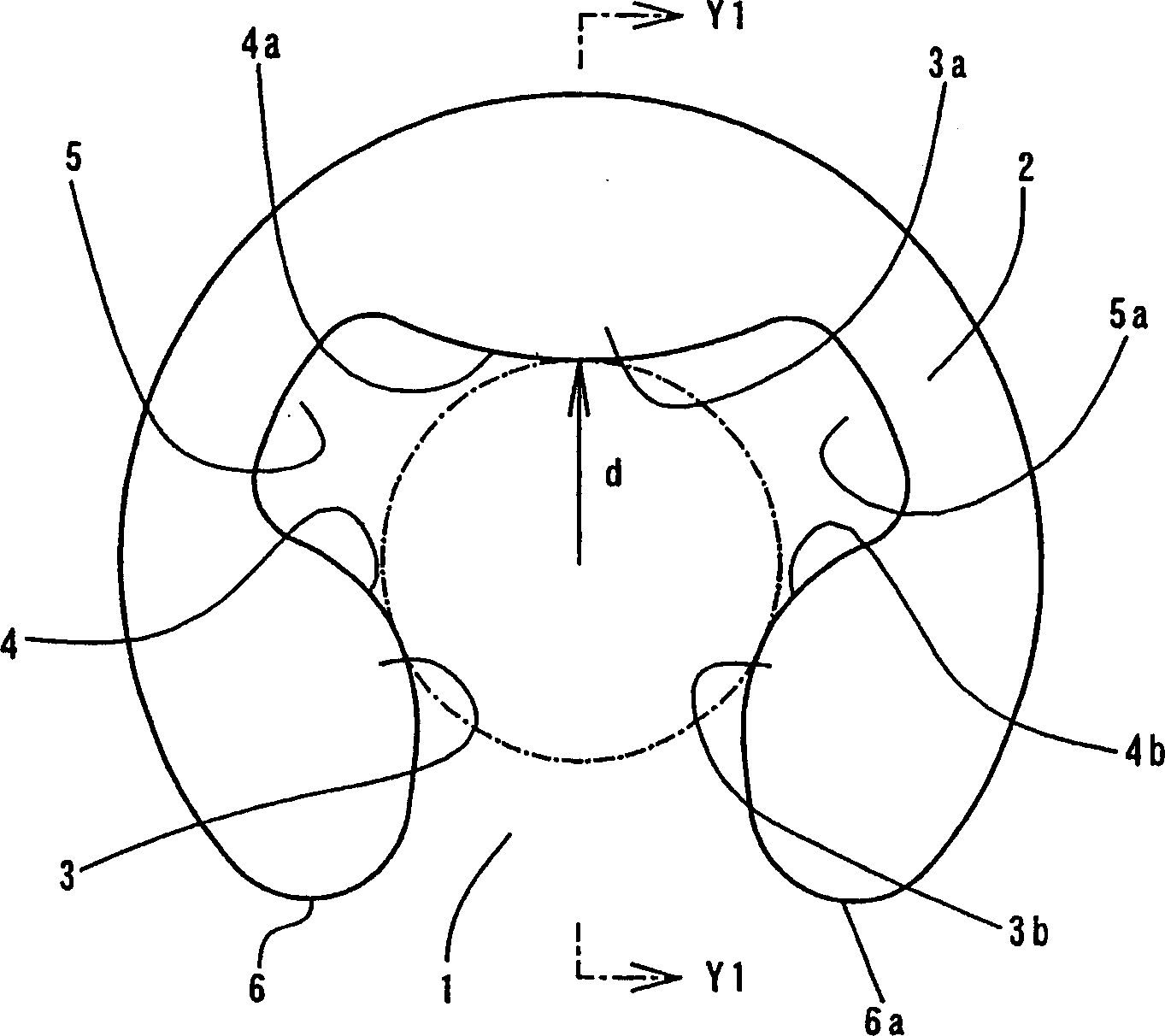
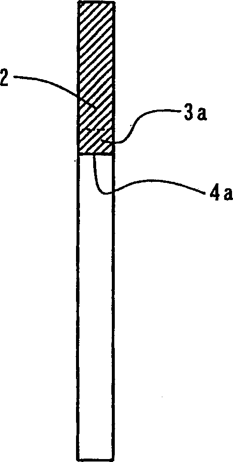
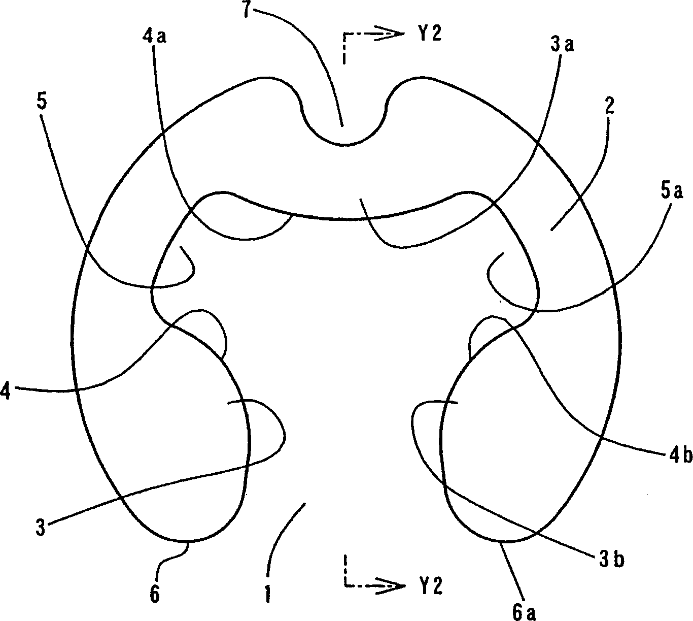
[0039] The shaft positioning ring according to one embodiment of the present invention is punched symmetrically. On the inner periphery of the C-shaped base material 2 are integrally formed a plurality of lobes 3, 3a, . . . which function as protrusions. The base material 2 has an opening portion 1 at one position on the outer periphery thereof. In this way, the inner edges 4, 4a... of the lobes 3, 3a... are formed into a convex arc shape which circumscribes the outer peripheral surface of the mounting area on the axis S. As shown in FIG. The spaces between adjacent lobes 3, 3a are made as inner notches 5, 5a....

[0040] The base material 2 is made of a metal having excellent elasticity, such as spring steel or spring stainless steel. The diameter of the circle tangent to the inner edges 4, 4a... of all lobes 3, 3a... is set to be slightly smaller than the dia...


PUM


Abstract

Respective portions to contact a shaft do not contact the shaft in a stable condition. At least three projections 3, 3 a, . . . are formed in an inner periphery of a C-shaped base material 2 that has an opening portion 1 at one place of an outer periphery that expands toward the outer circumference, and spaces between the adjacent projections 3, 3 a, . . . are made inner notches 5, 5 a, . . . . Inner edges of the projections 3, 3 a, . . . are shaped like a convex circular arc circumscribed to an outer circumferential surface of a mounting region of the shaft S. Thus, the respective projections 3, 3 a, . . . can abut the shaft at one point, so that the retaining ring for shaft of the present application can be mounted to the shaft in a good posture.

Description

technical field [0001] The invention relates to a positioning ring for a shaft, which is fitted into an annular groove of the shaft, for positioning or preventing possible falling of components mounted on the shaft, such as bearings. Background technique [0002] As a conventional positioning ring for shafts, the "E type positioning ring" stipulated in JIS (Japanese Industrial Standard) 2805 is a typical structure. The E-type positioning ring should be made of spring steel or spring stainless steel, and its inner diameter is slightly smaller than the diameter of the annular groove. Among them, there are notches at two positions on the inner periphery to facilitate elastic deformation, and on the outer peripheral surface An opening portion is provided at one of the positions. Thus, this structure can achieve the following effects: the E-type positioning ring can be installed by using a manually held tool, and the E-type positioning ring is placed at the top of the tool, or t...

Claims


Application Information

Patent Timeline
Patent Type & Authority Applications(China)
IPC IPC(8): F16B21/18
CPCF16B21/186F16B21/18
Inventor 田中耕一田中良亲
Owner CHUBU BEARING SEISAKUSHO
Why Eureka
Try Eureka