

Fuel injection valve
A fuel injection valve and fuel technology, applied in the directions of fuel injection device, injection device, charging system, etc., can solve the problem of inability to obtain fuel flow, unreasonable relative position relationship between valve seat hole and fuel injection hole, insufficient atomization, etc. problem, to achieve the effect of reducing exhaust emissions, stabilizing direction and shape, and preventing retention
- Summary
- Abstract
- Description
- Claims
- Application Information
AI Technical Summary
Problems solved by technology
Method used
Image

Examples
Embodiment 1
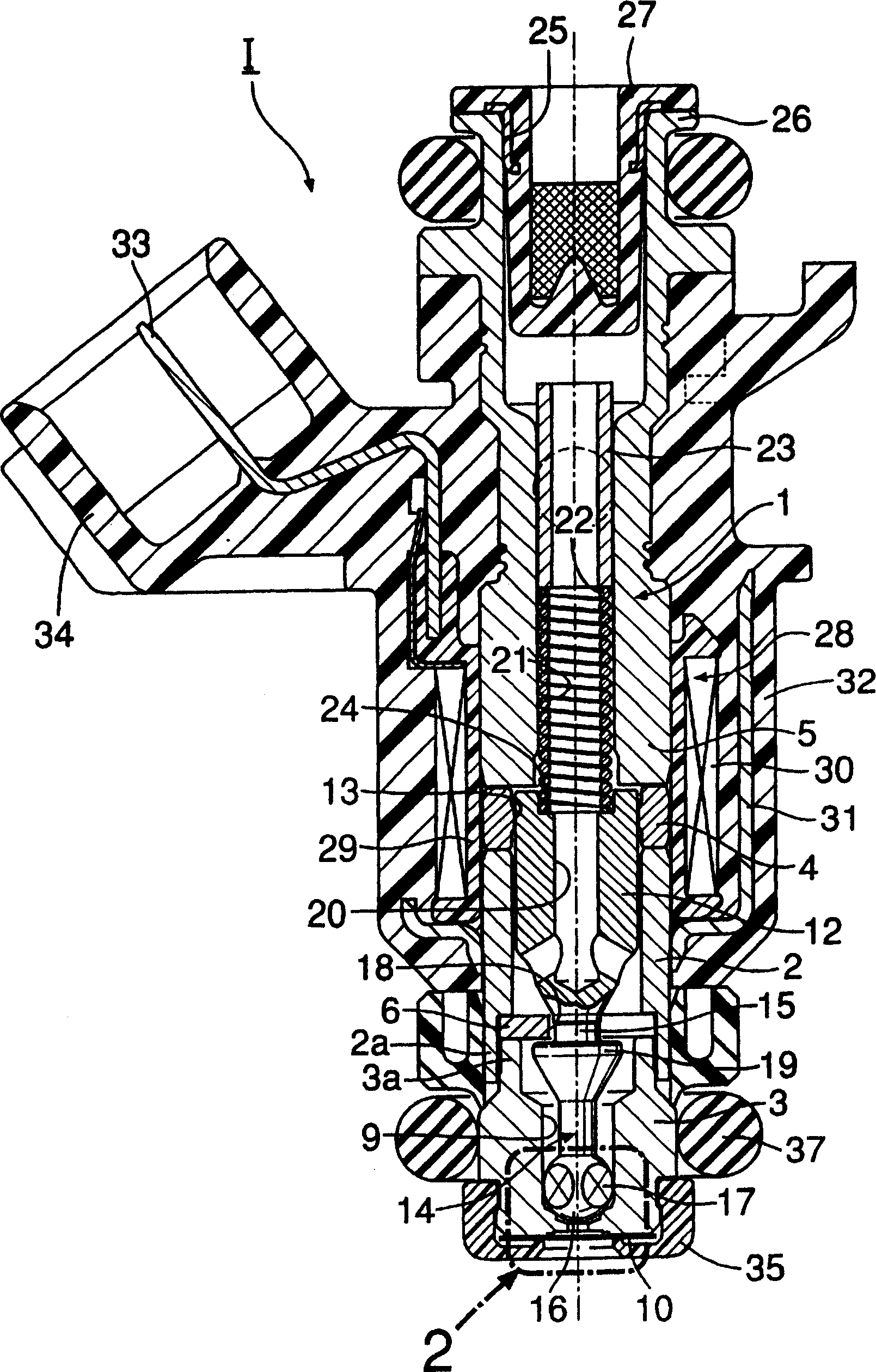
[0037] exist figure 1 Among them, the housing 1 of the electromagnetic fuel injection valve 1 for an internal combustion engine is composed of the following components: a cylindrical valve housing 2 (magnetic body); The valve seat member 3; the cylindrical fixed core 5 that is liquid-tightly combined with the rear end of the valve housing 2 via an annular spacer 4.
[0038] The spacer 4 is made of non-magnetic metal, such as stainless steel. The valve casing 2 and the fixed iron core 5 abut against the two ends thereof, and are welded together in a liquid-tight manner along the entire circumference.
[0039] A first fitting cylindrical portion 3 a and a second fitting cylindrical portion 2 a are respectively formed at opposing end portions of the valve seat member 3 and the valve housing 2 . Furthermore, the first fitting cylindrical portion 3 a is pressed into the second fitting cylindrical portion 2 a together with the baffle 6 , and the baffle 6 is sandwiched between the v...
Embodiment 2
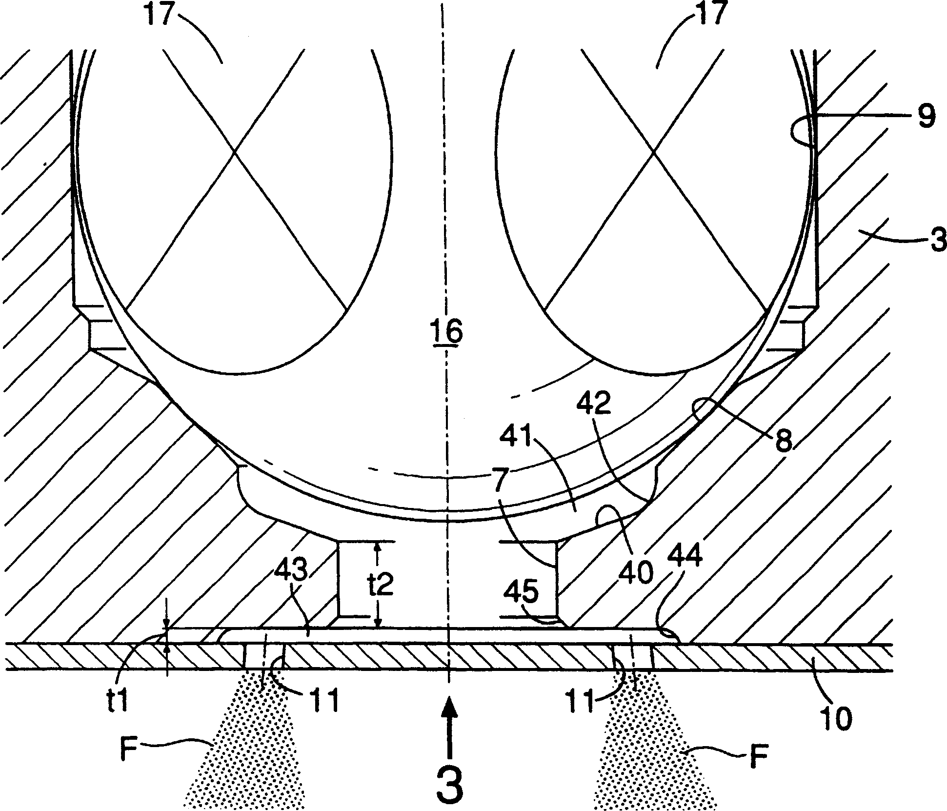
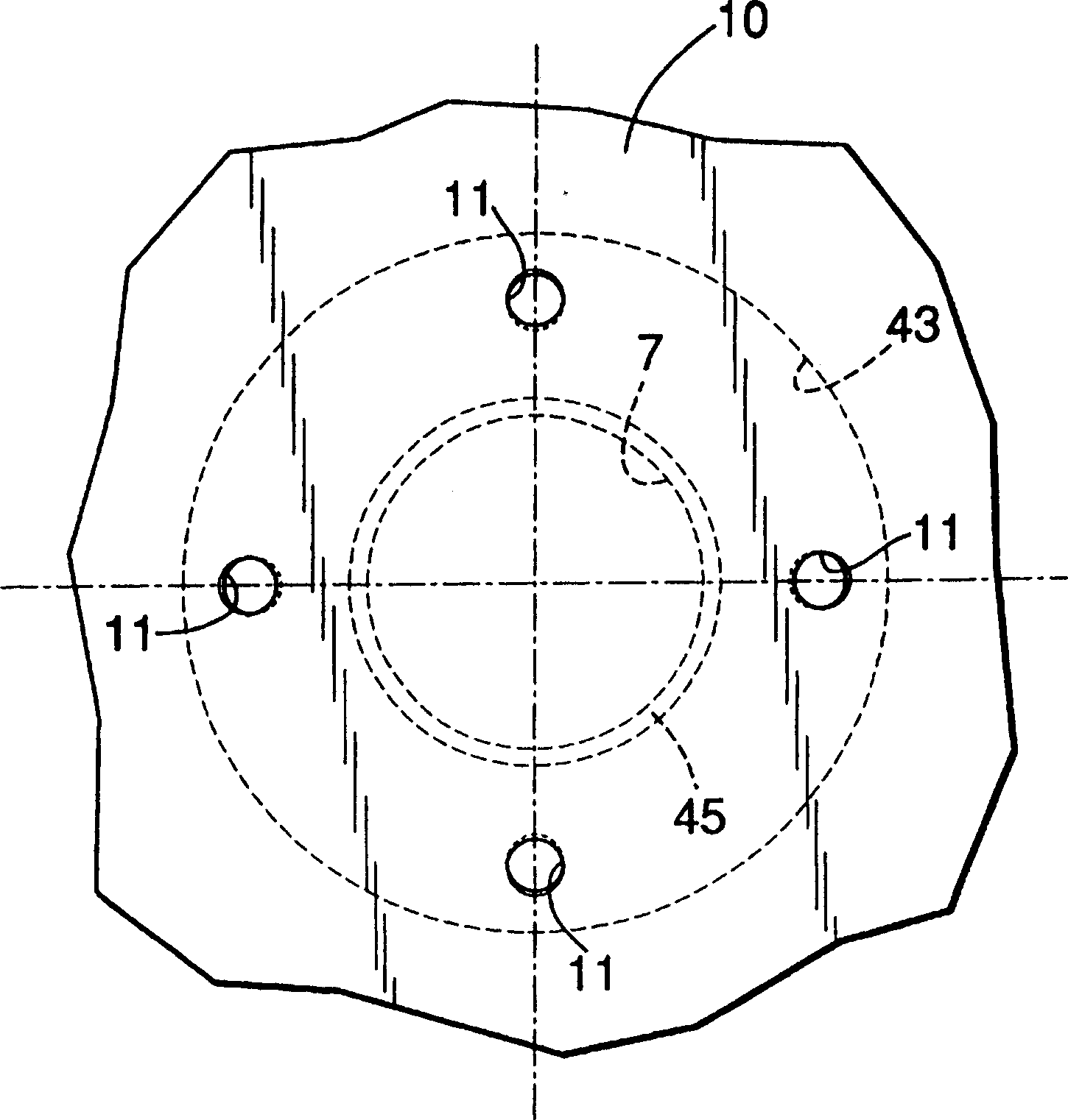
[0070] In this second embodiment, on the top surface of the fuel diffusion chamber 43, one or more stages of annular steps 43a concentric with the valve seat hole 7 are formed, whereby the height t1 of the fuel diffusion chamber 43 increases as the fuel diffusion chamber increases. The central portion of the diffusion chamber 43 gradually decreases toward the radially outward. The above-mentioned step portion 43a is formed in a cone shape or an arc shape so as not to hinder fuel diffusion. In addition, a tapered or arcuate chamfer 42 ′ is provided at an annular corner portion connecting the bottom surface of the fuel collection chamber 41 and the inner peripheral surface of the valve seat hole 7 .
[0071] Other constitutions are identical with above-mentioned embodiment, therefore, in Figure 4 In , the parts corresponding to the above-mentioned embodiments are assigned the same reference numerals, and their descriptions are omitted.
[0072] According to the second embodim...
Embodiment 3
[0075] In the third embodiment, an intermediate plate 50 having an opening 50 a corresponding to the fuel diffusion chamber 43 is joined between the valve seat member 3 and the injection plate 10 . Other constitutions are identical with above-mentioned embodiment, therefore, in Figure 5 In , the parts corresponding to the above-mentioned embodiments are assigned the same reference numerals, and their descriptions are omitted.
[0076] According to the third embodiment, the fuel diffusion chamber 43 can be easily formed by pressing the intermediate plate 50 .
PUM
 Abstract
Description
Claims
Application Information