Side lighting type lens assembly

A lens group, lighting technology, applied in lenses, optics, instruments, etc., can solve problems such as affecting the light output efficiency of the lens, damage to fragile structures, etc.

Active Publication Date: 2006-11-22
TCL CHINA STAR OPTOELECTRONICS TECH CO LTD
View PDF0 Cites 5 Cited by
  • Summary
  • Abstract
  • Description
  • Claims
  • Application Information

AI Technical Summary

Problems solved by technology

[0003] However, the small-angle light beam near the main axis 10 cannot be deflected to both sides by using the two optical paths provided by the lens, so that the light beam is directly emitted upward, which will cause a bright spot directly above LED1
[0004] Furthermore, the junction between the reflective surface 12 and the first refracting surface 13 is at an acute angle and is very thin. During the manufacture, transportation or use of the lens, a slight collision can easily cause damage to this fragile structure, thereby affecting the light output of the lens. efficiency

Method used


Image

  • Side lighting type lens assembly
  • Side lighting type lens assembly
  • Side lighting type lens assembly

Examples


Embodiment Construction

[0020] The aforementioned and other technical contents, features and effects of the present invention will be clearly presented in the following detailed description of two preferred embodiments with reference to the drawings.

[0021] Before the present invention is described in detail, it should be noted that in the following description, similar elements are denoted by the same reference numerals.

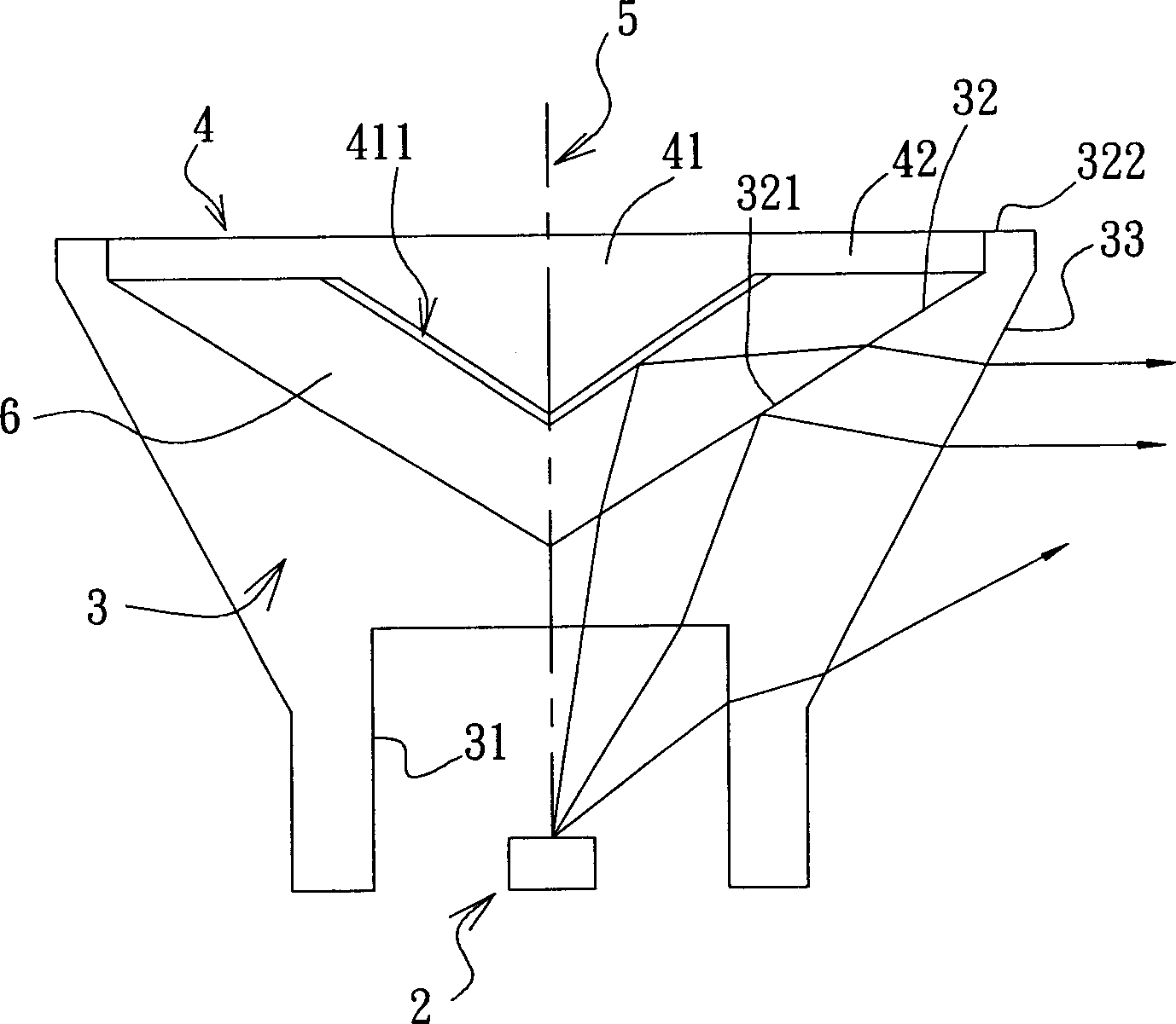
[0022] refer to figure 2 , the first preferred embodiment of the side-illuminated lens group of the present invention is used to guide the light beam emitted by a light-emitting element 2 to emit sideways. In this example, the light-emitting element 2 is illustrated with an LED as an example. A cup body portion 3 and a cover body portion 4 .

[0023] The cup body 3 is a transparent body, and its material includes but not limited to polymethylmethacrylate (polymethylmethacrolate; PMMA) or polycarbonate (polycarbonate; PC). A central axis 5 passing through the LED is defined, w...


PUM


Abstract

The disclosed lateral lighting lens group comprises: a cup body with a bottom surface toward the luminous element, a top surface with an inner surface to total reflect entered beam, and a surrounding surface; and a cover body on top of former top surface with a reflection surface toward the luminous element. This invention can enhance structure strength and reduces lens damage.

Description

【Technical field】 [0001] The invention relates to a lens, in particular to a side-illumination lens group. 【Background technique】 [0002] refer to figure 1 A known side-illuminated light-emitting diode (LED) lens mainly includes a bottom surface 11 facing the LED1, a reflective surface 12 opposite to the bottom surface 11, a first refracting surface 13 on the side and at an oblique angle to the main axis 10, and The second refraction surface 14 connecting the bottom surface 11 and the first refraction surface 13 . The conventional lens structure mainly divides the light beam emitted by the LED1 into two light paths. One, the light beam that enters through the bottom surface 11 and forms a small angle with the main axis 10 is totally reflected on the reflective surface 12 and then passes through the first refracting surface 13 is refracted horizontally out of the lens. Another optical path is that the light beam entering through the bottom surface 11 and forming a relativ...

Claims


Application Information

Patent Timeline
Patent Type & Authority Applications(China)
IPC IPC(8): G02B3/00
Inventor 刘明达陈皇任
Owner TCL CHINA STAR OPTOELECTRONICS TECH CO LTD
Why Eureka
Try Eureka