
Power amplifier

A path and peak technology, applied in the field of power amplifier technology, can solve problems such as the impact of the pass-through rate, not completely solved, and the difference in the efficiency of Doherty power amplifiers, to achieve the effect of improving flexibility, improving overall efficiency, and reducing the difficulty of mass production

Inactive Publication Date: 2006-11-22
HUAWEI TECH CO LTD
View PDF0 Cites 19 Cited by
  • Summary
  • Abstract
  • Description
  • Claims
  • Application Information

AI Technical Summary

Problems solved by technology

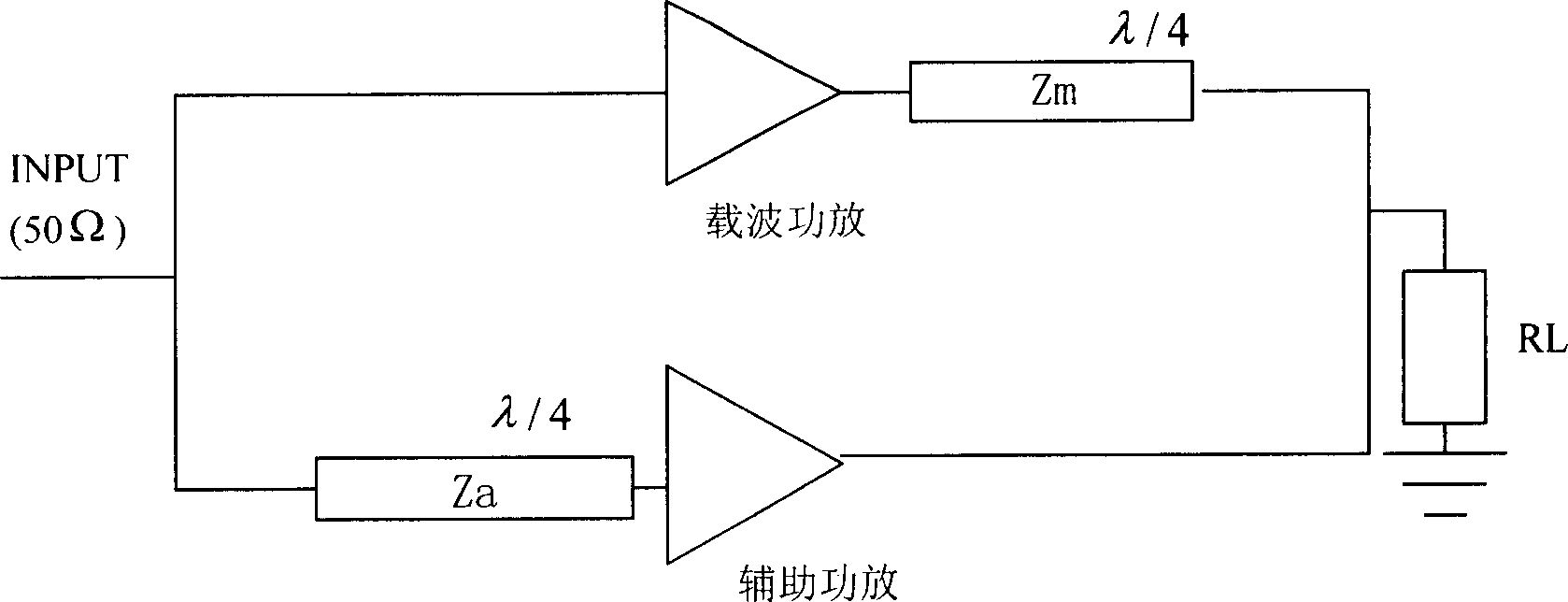
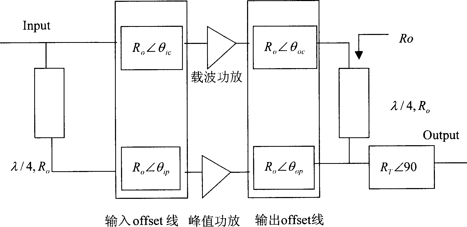
[0008] 1. Due to the discrete nature of power amplifier components, there will be differences in the phase and test characteristics of each peak power amplifier and carrier power amplifier, and it is impossible to adjust as accurately as in the laboratory during production figure 2 Therefore, these offset lines in the production may have an impact on the production straight-through rate, making it difficult to ensure mass production of components
[0009] 2. Since the peak power amplifier generally works in class C, its gain and phase characteristics will change significantly with its input power. Therefore, it is difficult to ensure that the power amplifier is in a large dynamic range with the existing technology. Presents the ideal Doherty power amplifier characteristics, so there is still a difference between the efficiency of the designed power amplifier and the efficiency of the ideal Doherty power amplifier
[0010] 3. Since the carrier power amplifier is generally biased in class AB, and the peak power amplifier is generally biased in class C, the carrier power amplifier will have a greater gain than the peak power amplifier, so that a considerable part of the driver stage power will be lost before the peak power amplifier starts to work. consumed by the peak power amplifier, thereby reducing the average efficiency of the power amplifier
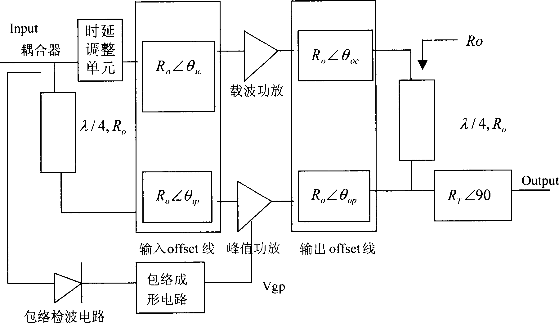
[0012] use image 3 The scheme shown can smooth and improve the gain difference between the two channels of the peak power amplifier and the carrier power amplifier, and make the characteristics of the entire power amplifier closer to the ideal Doherty characteristics, thereby improving the performance of the power amplifier to a certain extent, but it does not Completely solve the problems mentioned in the prior art one, it still has the following defects:
[0013] Since the phase characteristics of the Class C power amplifier will change with the change of its gate voltage, the phase difference between the signal path of the peak power amplifier and the carrier power amplifier will still change with the output power. The ideal required by the Doherty power amplifier The load-pull characteristics of this kind of power amplifier cannot be realized, and the problem that the peak power amplifier loses a certain driving power before starting to work still exists, and the mass production characteristics of this kind of power amplifier are still questionable

Method used


Image

  • Power amplifier
  • Power amplifier
  • Power amplifier

Examples


Embodiment Construction

[0048] For the power amplifier device described in the present invention, the present invention provides a first embodiment, which is as follows Figure 4 As shown, it includes: offset line input unit, carrier power amplifier, peak power amplifier, offset line output unit, amplitude adjustment unit and phase adjustment unit set on the signal path of the peak power amplifier, and a monolithic amplifier set on the peak power amplifier path, The driver stage amplifier and the final stage amplifier, the monolithic amplifier arranged on the path of the carrier power amplifier, the driver stage amplifier, the final stage amplifier and the time delay adjustment unit arranged between the monolithic amplifier and the driver amplifier.

[0049] The offset line input unit inputs the offset line to the carrier power amplifier and the peak power amplifier through the monolithic amplifier, the driver stage amplifier and the final stage amplifier respectively, and adjusts the signal path of t...


PUM


Abstract

The invention discloses a power amplifier device, which is characterized by the following: the signal amplitude and signal phase of crest value power amplifier route or carrier power amplifier route are adjusted by phase-adjusting unit; the invention realizes active load drag and improves the overall efficiency of Doherty power amplifier; the system adjustment phase shifter and attenuator control voltage to adjust the amplitude and phase, so the problem of Doherty output measure is reduced; the flexibility of Doherty power amplifier design is improved.

Description

technical field [0001] The present invention relates to the communication field, in particular to a power amplifier technology. Background technique [0002] The power amplifier device is a key and core device in a modern wireless communication system. High power amplifier efficiency is of great help in reducing the operating costs of wireless operators and improving the reliability of the power amplifier. Among many high-efficiency power amplifier technologies, Doherty power amplifier technology is more and more popular in the industry because of its simple design and obvious improvement in power amplifier efficiency. It is considered by most people to be the mainstream technology of power amplifiers in the future. The following is a brief description of the traditional Doherty power amplifier technology: [0003] Doherty power amplifier is a power amplifier efficiency enhancement technology. By using two different types of power amplifier components to bear different inpu...

Claims


Application Information

Patent Timeline
Patent Type & Authority Applications(China)
IPC IPC(8): H03F3/20
Inventor 吴剑锋
Owner HUAWEI TECH CO LTD
Learn More