Wireless network system and capacity expansion method

A wireless network system and network technology, applied in the field of networking of communication systems, to achieve the effect of solving the problem of expansion contradictions, smooth expansion, and low-cost coverage

Active Publication Date: 2006-11-22
HUAWEI TECH CO LTD
View PDF0 Cites 4 Cited by
  • Summary
  • Abstract
  • Description
  • Claims
  • Application Information

AI Technical Summary

Problems solved by technology

[0016] The purpose of the present invention is to provide a wireless network system and a capacity expansion method to solve the problems existing in the "one-time planning" networking mode in the prior art, and to provide a smooth expansion network implementation scheme for the wireless communication system

Method used


Image

  • Wireless network system and capacity expansion method
  • Wireless network system and capacity expansion method
  • Wireless network system and capacity expansion method

Examples


Embodiment 1

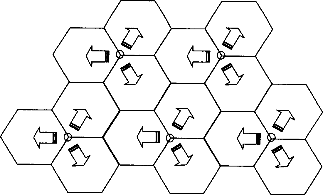
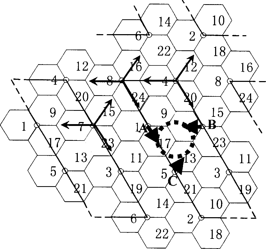
[0067] When expanding the capacity of an existing wireless communication network for the first time, refer to Figure 8c , you can use two two-way combiners to connect to the antenna port to obtain two cells divided into two to achieve capacity expansion. Among them, there are many ways to divide the cells. Taking the left and right separation along the antenna pointing as an example, it is required to obtain the combined outline and Figure 9 same. However, in practical applications, the split pattern usually cannot completely achieve the ideal model, but can only be approximated step by step. For example, an actual pattern such as Figure 10 As shown, there is a certain overlapping area between the two patterns at the interface in the middle, and when the overlapping area is small, the impact on the capacity is small. At this time, the vertical plane pattern does not change.

[0068] Since the coverage area of ​​the antenna is the same as before during capacity expansion,...

Embodiment 2

[0070] when based on Figure 10 When further expansion is required, refer to Figure 8d with Figure 8e , at this time, the vertical plane pattern will also be split, such as Figure 11 As shown, specifically, a two-way combiner can be used to connect to the antenna port to obtain three cells divided into three, or, without using a combiner, to obtain four cells divided into four to realize capacity expansion. Other principles are similar to those of Embodiment 1, so no detailed description is given here.

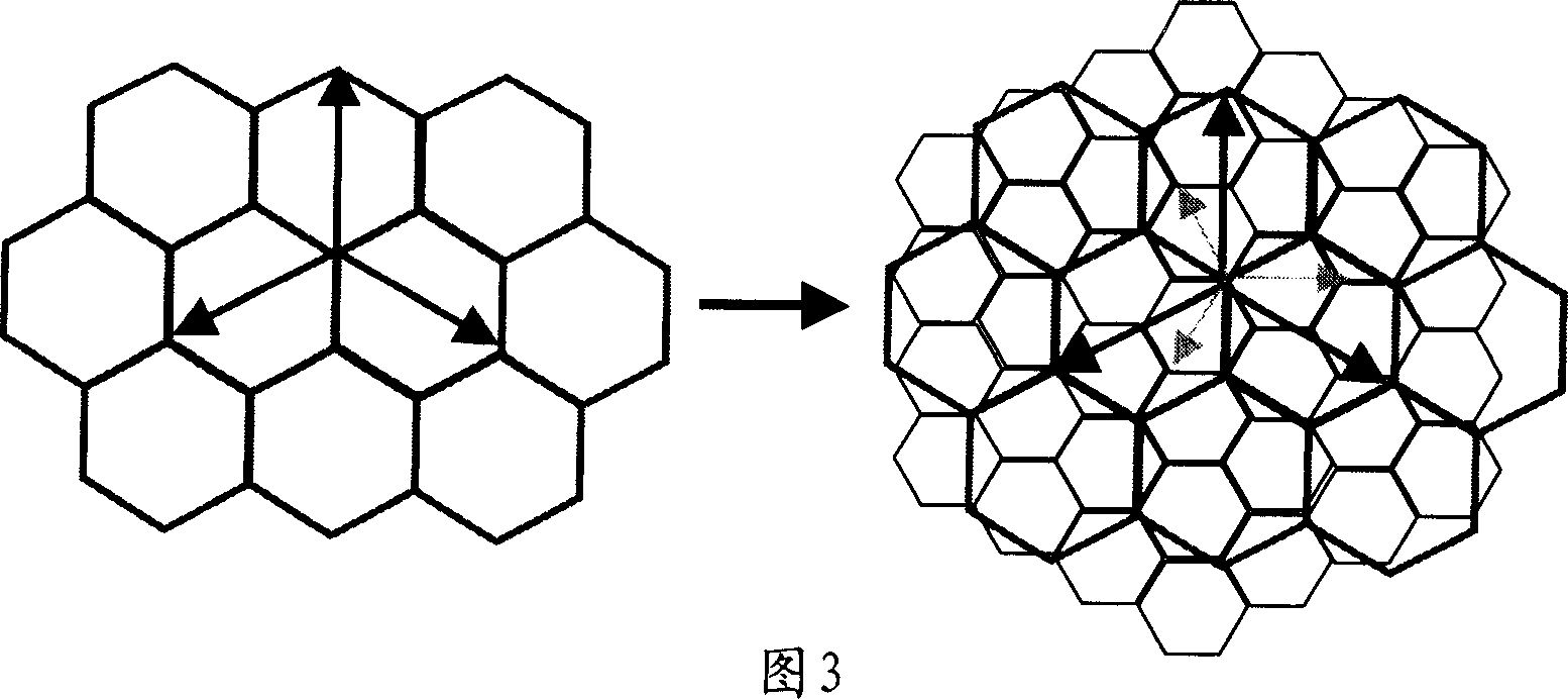
[0071] To sum up, the implementation of the present invention enables the network to perform low-capacity and low-cost coverage at the initial stage, and to realize very smooth capacity expansion without adding new sites. For example, if Figure 12 As shown, the technical solution provided by the prior art is not convenient for capacity expansion for local hotspots, but the technical solution provided by the present invention can easily realize smooth capacity expansion...


PUM


Abstract

The invention relates to a wireless network system and relative capacity expanding method. Wherein, it is characterized in that: in the wireless network system, using special antenna configuration to support the network combination and capacity expansion; it uses beehive section as unit to set one group of antennas, which is used to be related with one group of regions that covering the beehive section; each antenna is responsible to cover one section; said group of antenna can use the shaping antenna with several inputs. Therefore, the invention can make the network use low-capacity and low-cost cover at the start, and realize smooth capacity expansion without increasing new station.

Description

technical field [0001] The invention relates to wireless communication technology, in particular to the networking technology of the communication system of the third generation WCDMA and CDMA2000 (abbreviated as 3G system). Background technique [0002] A mobile communication system is composed of many base stations (called BTS), and each base station covers a service area to provide services for user terminals in the coverage area. The coverage area of ​​the base station is like a cell, so it is also called "cellular system". [0003] The existing wireless cellular systems are basically built in the form of three sectors, such as figure 1 As shown, the circle in the figure indicates the location of the base station, and the arrow indicates the direction of the base station antenna. In this structure, the directions of the antennas are staggered from each other. Therefore, the three-sector network construction method has the antenna pattern and the coverage area to form th...

Claims


Application Information

Patent Timeline
Patent Type & Authority Applications(China)
IPC IPC(8): H04W16/28
Inventor 李亚锐郭宽新应关祥
Owner HUAWEI TECH CO LTD
Why Eureka
Try Eureka