Contact plate, fixing belt thereof, package equipment and package conformation articles thereof

A contact plate and equipment technology, applied in the field of packaging equipment and packaging structures, can solve the problems of misalignment of end faces, adverse effects on the shape and performance of plasma display panels, and the inability to prevent misalignment of end faces of winding films, etc., and achieve the effect of improving operating efficiency

Inactive Publication Date: 2006-11-29
JSR CORPORATIOON
View PDF2 Cites 15 Cited by
  • Summary
  • Abstract
  • Description
  • Claims
  • Application Information

AI Technical Summary

Problems solved by technology

[0004] However, since the transfer film for forming electronic equipment parts must protect the film thickness and shape of the paste layer, it cannot be wound too tightly on the core. Therefore, it is easy to cause misalignment of the end surface due to impact during transportation, etc. Fortunately, in the conventional packaging boxes including the above-mentioned patent documents, etc., the status quo that the end face misalignment of the wound film cannot be reliably prevented is maintained.
Such misalignment of the end face will cause damage to the paste layer, which will adversely affect the shape and performance of the final product such as a plasma display panel, so it becomes a problem

Method used


Image

  • Contact plate, fixing belt thereof, package equipment and package conformation articles thereof
  • Contact plate, fixing belt thereof, package equipment and package conformation articles thereof
  • Contact plate, fixing belt thereof, package equipment and package conformation articles thereof

Examples


Embodiment

[0107] Hereinafter, the present invention will be described in more detail with reference to the drawings

[0108]

[0109] The following reference Figure 1 ~ Figure 6 The first embodiment of the present invention will be described.

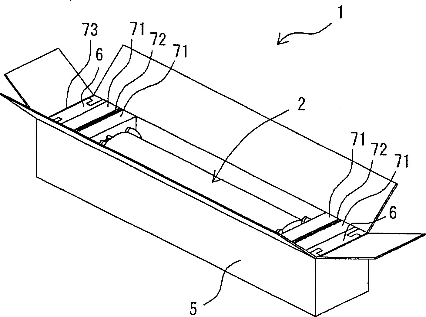
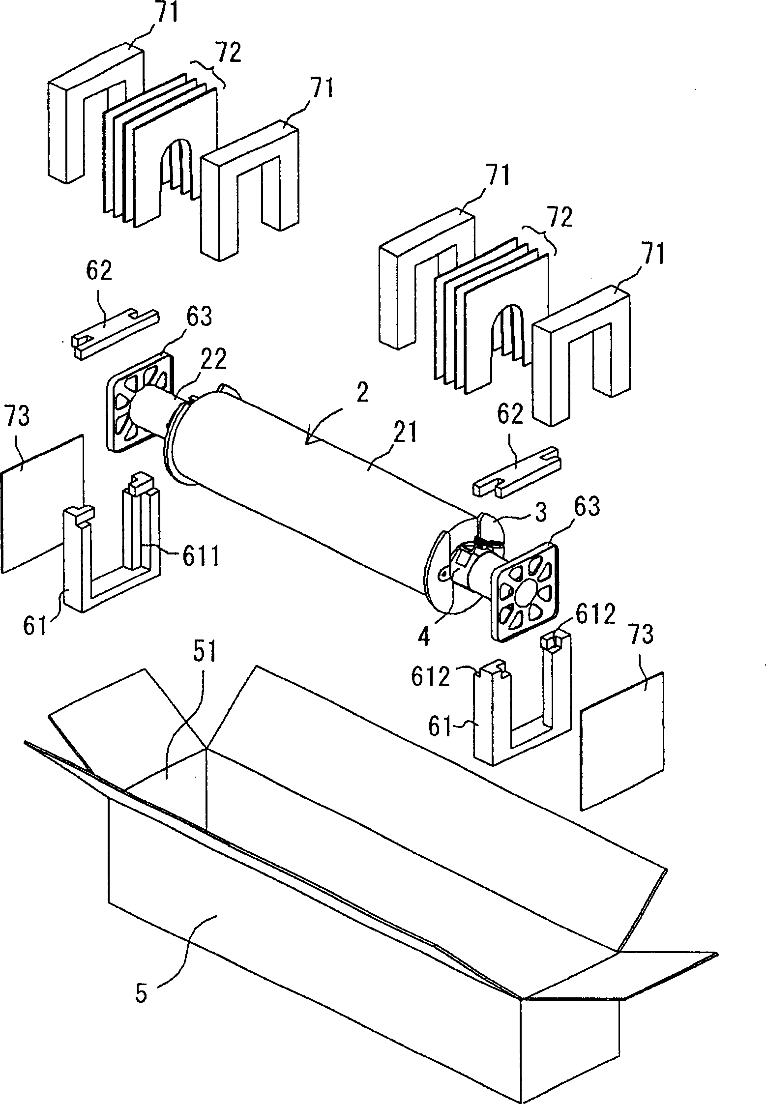
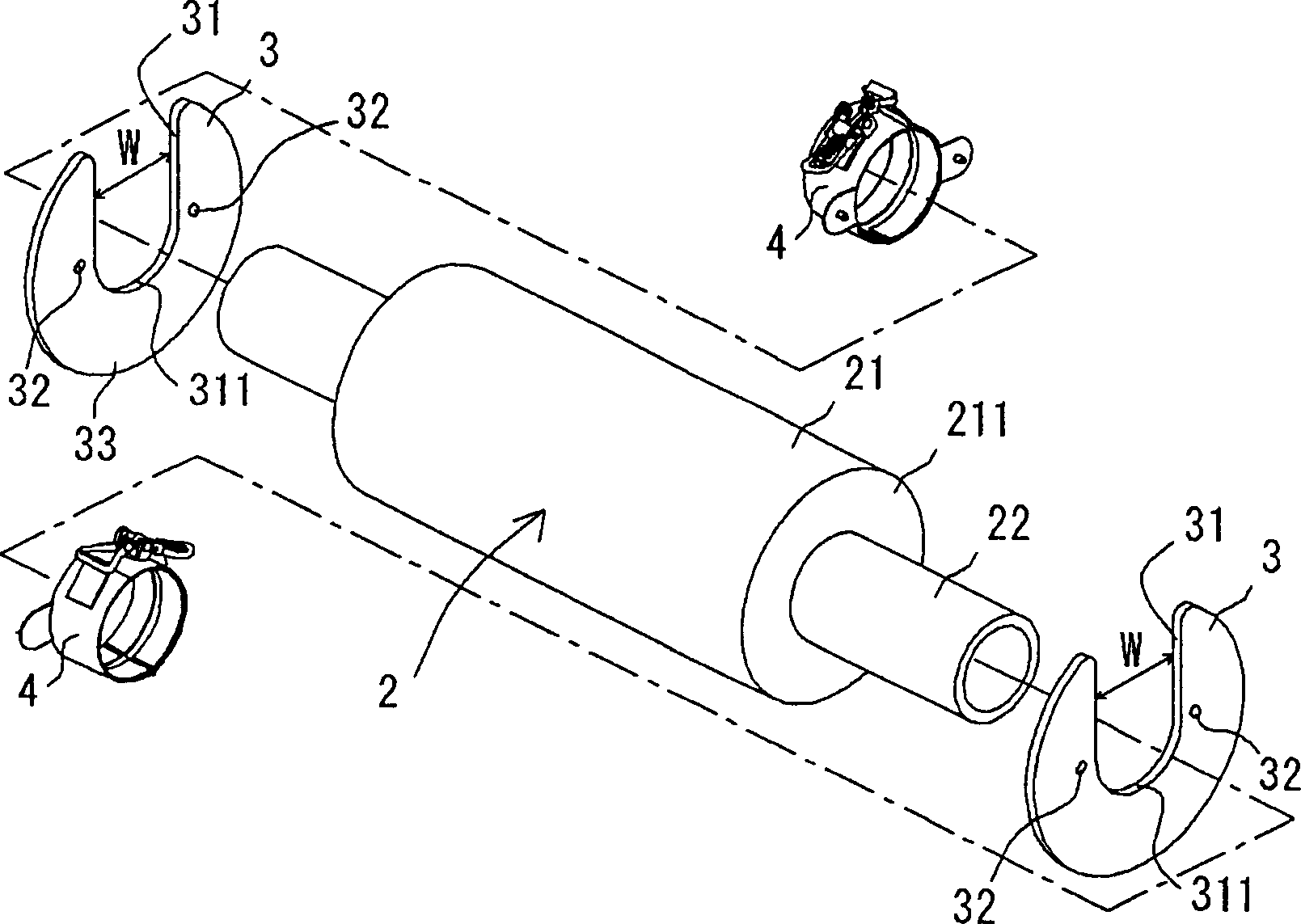
[0110] here, figure 1 It is a perspective view showing an example of a packaging structure obtained by wrapping a winding body obtained by winding a film for forming electronic device parts on a core, and packaging it in the packaging device of the present invention, figure 2 It is an exploded perspective view explaining the packaging structure. In addition, image 3 Is description figure 2 An exploded perspective view of the winding body in. In addition, Figure 4 Yes image 3 An enlarged view of the middle strap, Figure 5 It is the bottom view of the fixing belt. and, Figure 6 It is an explanatory diagram explaining the fixing band.

[0111] in figure 1 with figure 2 The winding body 2 contained in the box 5 of the packaging structure 1 sh...


PUM


Abstract

This invention provides a contact plate, which has an upstanding end surface retentively on the coiling body coiled with electronic machine parts forming film, and can prevent the end surface dislocation caused by the strike during the transportation, the fixing belt thereof, and packing tools and materials equipped with the contact plate and supporting belts. The packing tools of this invention comprise a chest(5) with a taking-in coiling body(2); the coiling body(2) has a coiling core(22) and electronic machine parts forming film(21) coiled around the coiling core(22), characterizing: inside the said chest(5) installs the contact plate(3) and the fixing belt(4); the surface of the said contact plate(3) contacts the surface coiled with the said electronic machine parts forming film(21); the said fixing belt(4) has a flange which presses the said contact plate(3) and is located on the opposite side of the said electronic machine parts forming film(21), and is installed in a free loading and unloading form on the said coiling core(22).

Description

Technical field [0001] The present invention relates to a contact plate, its fixing belt, and packaging equipment and packaging structures having them. More specifically, it relates to a contact plate that has excellent end surface retention on a wound body wound with a film for forming electronic device parts, and can prevent end surface misalignment caused by impacts during transportation, etc., its fixing tape, and packaging with them Equipment and packaging structures. Background technique [0002] Conventionally, in order to form components such as dielectric layers, electrodes, separators, phosphors, resistors, color filters, and black matrices in electronic devices such as plasma display panels, long strip-shaped transfer films have been used. [0003] This kind of transfer film is produced by forming a paste-like material layer on a plastic support film, and is usually wound on a cylindrical core or the like to make a roll, and then it is stored in a packaging box. Carry ...

Claims


Application Information

Patent Timeline
Patent Type & Authority Applications(China)
IPC IPC(8): B65D85/66B65D25/10B65D77/26
CPCB65D5/5002B65D25/101B65D85/04B65D85/66B65D2585/86
Inventor 宫岛秀树柴田幸知板野考史屉沼洋行坂井孝广菅野将功田中忠昭三田村贤治迎居浩昭
Owner JSR CORPORATIOON
Why Eureka
Try Eureka