
Process for producing a radiation source, and radiation source

A radiation source and radiation unit technology, applied in the field of radiation sources, can solve problems such as increased production costs of radiation sources, and achieve the effect of shortening the process chain

Inactive Publication Date: 2006-11-29
PATENT TREUHAND GESELLSCHAFT FUER ELECTRIC GLUEHLAMPEN M B H
View PDF0 Cites 4 Cited by
  • Summary
  • Abstract
  • Description
  • Claims
  • Application Information

AI Technical Summary

Problems solved by technology

Both of these methods lead to increased production costs of the radiation source

Method used


Image

  • Process for producing a radiation source, and radiation source
  • Process for producing a radiation source, and radiation source
  • Process for producing a radiation source, and radiation source

Examples


Embodiment Construction

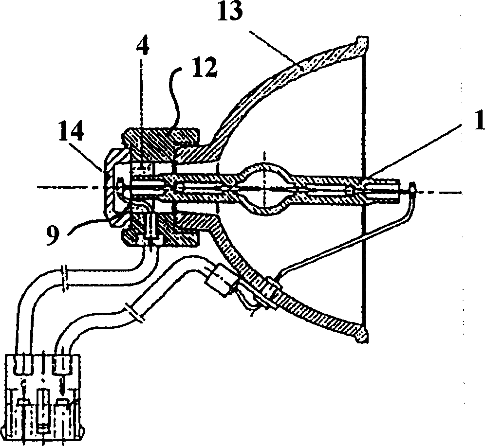
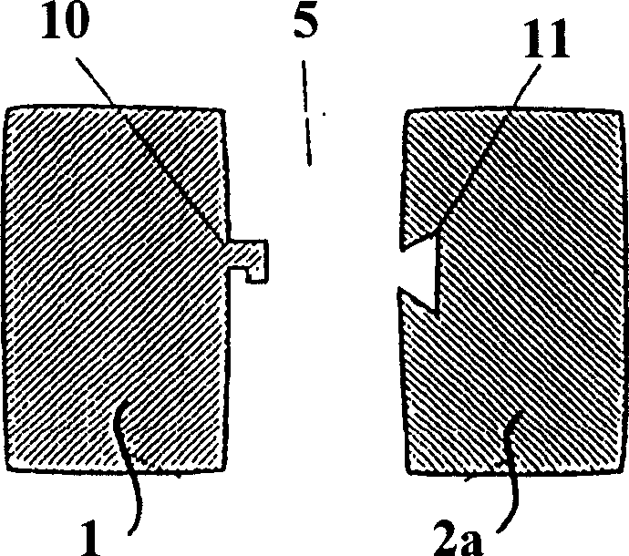
[0048] exist figure 1 The structure of the radiation source according to the invention is shown in the example of a cross-sectional view of a discharge lamp. The discharge lamp comprises a glass or ceramic part 1 in which a radiation element 8 is arranged. In the illustrated embodiment, the radiation elements 8 are two electrodes surrounded by gas. However, it is also conceivable for the radiation unit 8 to be formed, for example, from a coiled filament, or from electrodes in a vacuum.

[0049] The radiation unit 8 is connected to a power supply lead 9 . What is involved in the radiation source 8 shown is a preferably tubular discharge lamp with two opposite ends, so that the current supply leads 9 are also guided in two opposite directions. The discharge lamp shown is provided at each of its ends with a support 2a formed as a metal or ceramic base.

[0050] In the connecting region 3 there is a metal foam 4 which can connect the glass or ceramic part 1 to the support part...


PUM


Abstract

The invention relates to a process for producing a radiation source and to a radiation source with at least one glass or ceramic element and at least one carrier element, the glass or ceramic element and the carrier element being joined to one another by metal foam within a joining region. Optionally, the carrier element may itself be a part which consists of metal foam.

Description

technical field [0001] The invention relates to a method for producing a radiation source of the type according to claims 1 and 2, and a radiation source of the type according to claims 25 and 26 with at least one glass or ceramic part and at least one support part . [0002] The invention relates in particular to the manufacture of lamps, in particular discharge lamps as preferably used in lighting technology, domestic engineering and the automotive industry, as well as such radiation sources themselves. Furthermore, the present invention also relates to similar parts and assemblies with radiation sources, such as Braun tubes that can be used in television screens and computer monitors. Background technique [0003] Known radiation sources, especially incandescent and discharge lamps, usually consist of a glass or ceramic hollow body connected to one or more bases. In addition, conventional incandescent and discharge lamps have power supply leads connected to incandescent...

Claims


Application Information

Patent Timeline
Patent Type & Authority Applications(China)
IPC IPC(8): H01J9/26H01J9/30H01J9/32H01K1/38H01K1/36
CPCH01J61/523H01J5/58H01J9/34H01J61/36B22F2998/00H01K1/46B22F7/006B22F7/062B22F3/1125H01J9/24H01J9/02
Inventor T·希普科J·霍费尔德M·斯坦格C·维斯塞林
Owner PATENT TREUHAND GESELLSCHAFT FUER ELECTRIC GLUEHLAMPEN M B H
Learn More