

Flat type heat pipe
a heat pipe and flat-type technology, applied in the field of flat-type heat pipes, can solve the problems that the uniform-type wick structure cannot meet these requirements, and the heat pipe will suffer a dry-out problem at the evaporating section, and achieves the effects of low resistance, high capillary force, and high permeability of the first section
- Summary
- Abstract
- Description
- Claims
- Application Information
AI Technical Summary
Benefits of technology
Problems solved by technology
Method used
Image

Examples
first embodiment
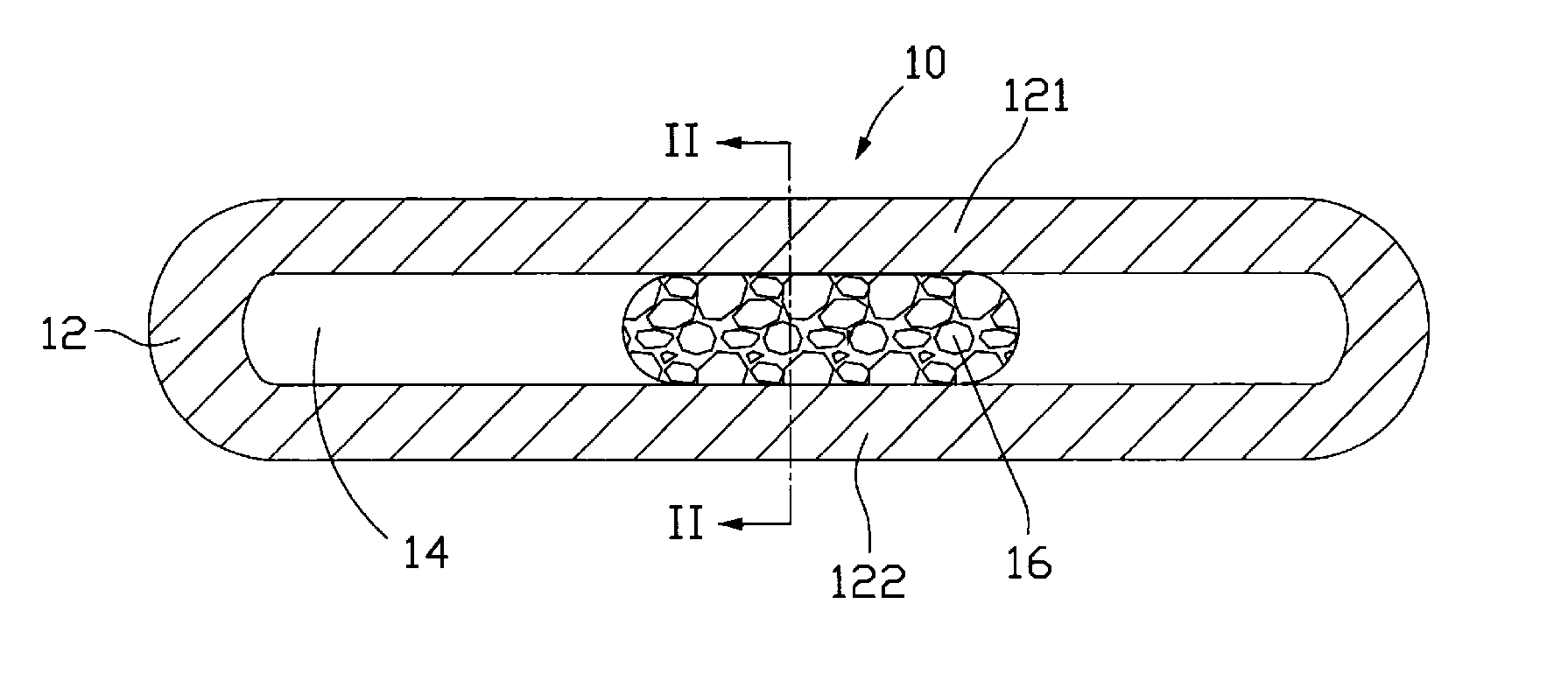
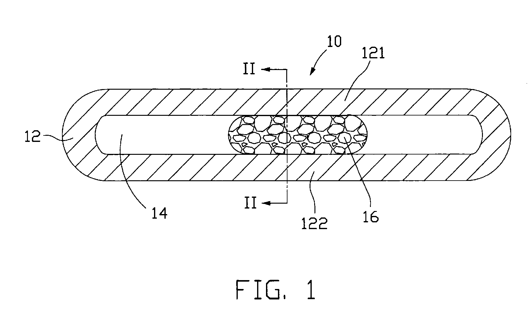
[0014]FIG. 1 illustrates a flat type heat pipe 10 in accordance with the present invention. The heat pipe 10 has a plate-type configuration and includes a metal casing 12. The metal casing 12 includes a top plate 121 and a bottom plate 122 cooperating with the top plate 121 to define a chamber 14 in the metal casing 12. A wick structure 16 is provided inside the heat pipe 10, occupying a central region of the chamber 14. The wick structure 16 is so dimensioned as to fit between the top and bottom plates 121, 122 of the metal casing 12. The metal casing 12 is made of high thermally conductive material such as copper or aluminum. The heat pipe 10 is evacuated and hermetically sealed after a working fluid (not shown) is injected into the chamber 14 of the metal casing 12. The working fluid is saturated in the wick structure 16 and is usually selected from a liquid such as water or alcohol, which has a low boiling point and is compatible with the wick structure 16. The wick structure 16...
second embodiment
[0019]FIG. 3 illustrates a flat type heat pipe 20 in accordance with the present invention. In addition to the wick structure 16 that is in the form of a metal foam, the heat pipe 20 also includes a plurality of fine grooves 201 longitudinally defined in an inner surface of the casing 22. These grooves 201 altogether function as another wick structure cooperating with the original wick structure 16 so as to obtain a higher capillary force inside the heat pipe 20. Furthermore, each of the grooves 201 may have a varying width throughout the heat pipe 20. As particularly shown in FIG. 4, each groove 201 has a width gradually increasing from the evaporating section 223 towards the condensing section 224 of the heat pipe 20. This particular design of the grooves 201 can reduce flow resistance to the condensate as it flows in the condensing section 224 of the heat pipe 20.
third embodiment
[0020]FIG. 5 illustrates a flat type heat pipe 30 in accordance with the present invention. In this embodiment, two wick structures 16 are arranged inside the heat pipe 30 with each being located near a sidewall of the heat pipe 30. Thus, the central region of the chamber of the heat pipe 30 functions as a vapor channel for passage of vapor generated inside the heat pipe 30 from the evaporating section to the condensing section.
PUM
 Abstract
Description
Claims
Application Information