Catalyst structure and method of fischer-tropsch synthesis

a technology applied in the field of catalyst structure and method of making, and a method of fischertropsch synthesis, can solve the problems of inability to improve conventional reactors, severe limitation of the reaction rate, and hot spots in the catalyst bed, so as to achieve no increase in methane selectivity, increase conversion, and increase the effect of conversion

Inactive Publication Date: 2006-01-03
BATTELLE MEMORIAL INST
View PDF32 Cites 39 Cited by
  • Summary
  • Abstract
  • Description
  • Claims
  • Application Information

AI Technical Summary

Benefits of technology

[0020]Advantages that may be provided by the invention include (i) at residence/contact times shorter than the prior art, higher conversions are achieved with no increase to methane selectivity; and (ii) as residence/contact times increase, con...

Problems solved by technology

However, the overall reaction rate is severely limited by heat and mass transfer with conventional catalysts or catalyst structures.
The limited heat transfer together with the fast surface reaction kinetics may result in hot spots in a catalyst bed.
Because of the necessary operational parameters to avoid methanation, conventional reactors are not improved even with ...

Method used


Image

  • Catalyst structure and method of fischer-tropsch synthesis
  • Catalyst structure and method of fischer-tropsch synthesis
  • Catalyst structure and method of fischer-tropsch synthesis

Examples


example 1

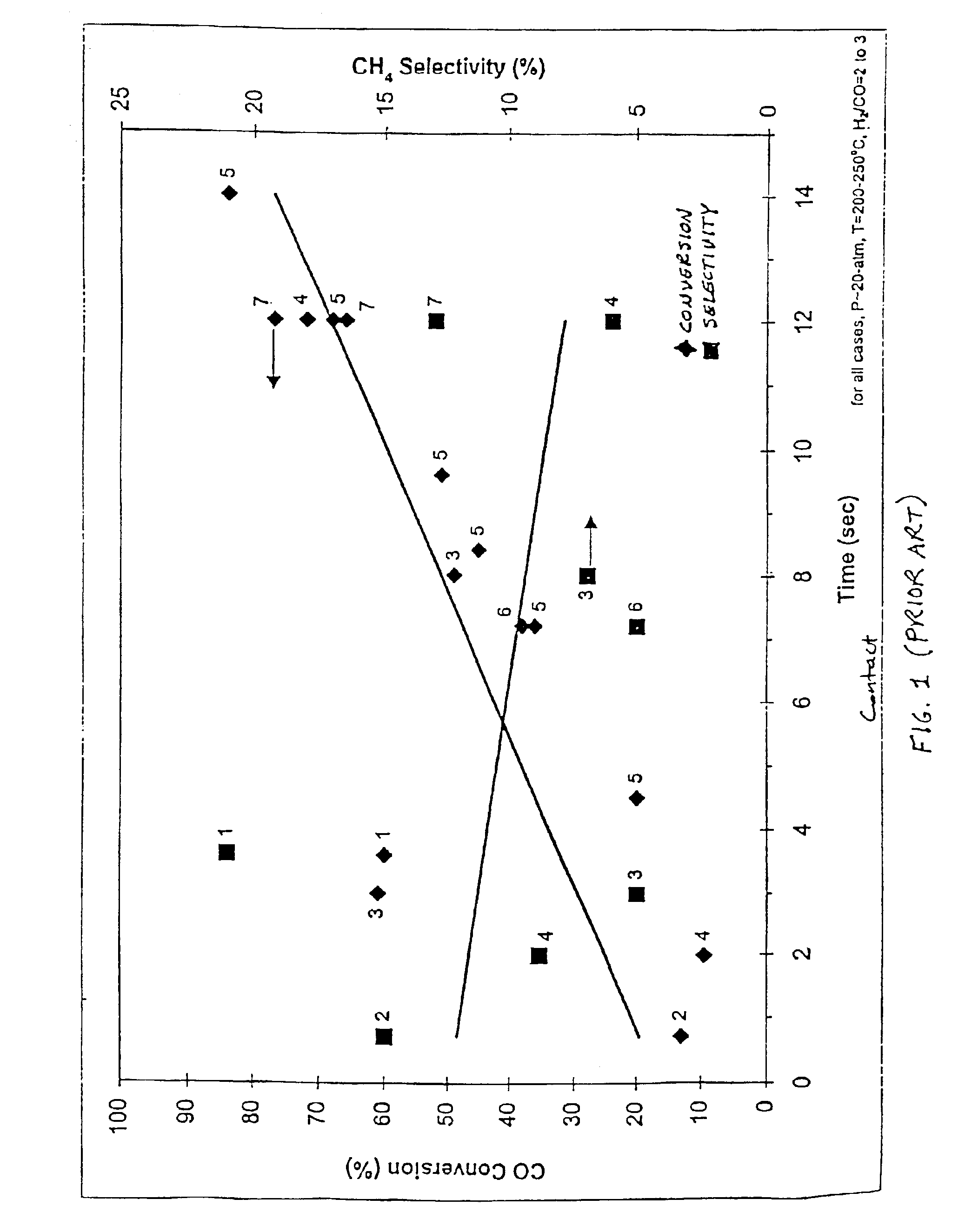
[0052]The effect of residence time and reaction temperature on the catalytic conversion of CO with H2 was examined in a constant flow reactor. The reactor was supplied with a mixture of feed gas, comprised of H2 and CO in a molar, or volumetric (assuming ideal gas behavior), ratio of H2 / CO=3. This reactant feed was fed into a reaction chamber, which was maintained at a constant temperature inside an isothermal furnace. The interior of the catalyst chamber measures 35.6-mm (1.4-in) in length, 1.5-mm (0.060-in) in thickness and 8-mm (0.315-in) in width. The reaction products then exited the reaction chamber and were collected and analyzed for composition.

[0053]The catalyst for this experiment was prepared as follows. First, acidic gamma-alumina support powder (Strem) was ground and sieved to between 70- and 100-mesh (150 to 220-micron), and calcined (stabilized) at 500° C. for several hours. This powder was then impregnated with a solution containing cobalt nitrate hexahydrate and rut...

example 2

[0062]An experiment was conducted to demonstrate operation at various pressures. The equipment was the same as in Example 1.

[0063]According to the literature, variation in pressure should only affect true residence time in Fischer-Tropsch synthesis. In other words, conventional wisdom in Fischer-Tropsch reactions is that reaction rate is proportional to pressure under identical residence time. However, as shown in Table E2-1, with the catalyst structure of the present invention, catalyst activity was unexpectedly enhanced as the pressure was decreased under the same residence time. This surprising result is attributed to the enhanced mass and heat transfer possible with the catalyst structure of the present invention.

[0064]

TABLE E2-1Engineered catalyst performance for Fischer-Tropsch synthesis atabout 250° C. under a constant residence time (i.e., temperature andpressure corrected contact time) of 12.5 seconds. The contact time at24 atm (absolute) is 1 sec.Pressure, atm(absolute)Con...

example 3

[0065]Use of acidic gamma alumina supported Co or Ru alone as a catalyst on the metal foam was also tested under the conditions of Example 1 and performance was found to be worse than that of bimetallic catalyst such as Co—Ru.


PUM

PropertyMeasurementUnit
Temperatureaaaaaaaaaa

Abstract

The present invention includes Fischer-Tropsch catalysts, reactions using Fischer-Tropsch catalysts, methods of making Fischer-Tropsch catalysts, processes of hydrogenating carbon monoxide, and fuels made using these processes. The invention provides the ability to hydrogenate carbon monoxide with low contact times, good conversion rates and low methane selectivities. In a preferred method, the catalyst is made using a metal foam support.

Description

RELATED APPLICATIONS[0001]This application is a divisional of U.S. Ser. No. 09 / 492,254, filed Jan. 27, 2000, now U.S. Pat. No. 6,558,634, which was continuation-in-part of U.S. Ser. No. 09 / 375,610, filed Aug. 17, 1999, now U.S. Pat. No. 6,451,864, which is incorporated by reference.FIELD OF THE INVENTION[0002]The present invention is a catalyst structure and method of making, and a method of Fischer-Tropsch synthesis.BACKGROUND OF THE INVENTION[0003]Fischer-Tropsch synthesis is carbon monoxide hydrogenation that is usually performed on a product stream from another reaction including but not limited to steam reforming (product stream H2 / CO˜3), partial oxidation (product stream H2 / CO˜2), autothermal reforming (product stream H2 / CO˜2.5), CO2 reforming (H2 / CO˜1) coal gassification (product stream H2 / CO˜1) and combinations thereof.[0004]Fundamentally, Fischer-Tropsch synthesis has fast surface reaction kinetics. However, the overall reaction rate is severely limited by heat and mass tra...

Claims


Application Information

Patent Timeline
IPC IPC(8): C07C27/00B01J8/02B01J12/00B01J19/24B01J23/89B01J35/00B01J35/10B01J37/02C07B61/00C07C1/04C07C9/02C07C9/04C07C9/15C10G2/00
CPCB01J8/0285C10G2/332B01J19/248B01J23/8913B01J35/0006B01J35/002B01J35/04B01J35/10B01J37/0221B01J37/0238B01J37/0244C07C1/041C07C1/0425C07C1/0455C10G2/33B01J12/007B01J2219/32293B01J2219/32296B01J2219/32408B01J2219/32466B01J2219/32475C07C2523/46C07C2523/745C07C2523/75B01J23/462B01J23/75B01J35/1009
Inventor WANG, YONGVANDERWIEL, DAVID P.TONKOVICH, ANNA LEE Y.GAO, YUFEIBAKER, EDDIE G.
Owner BATTELLE MEMORIAL INST
Why Eureka
Try Eureka