Transversal filter, transmitter and receiver with transversal filter

A technology of transversal filter and filter, applied in the direction of transversal filter, digital filter, filter, etc., to achieve the effect of minimizing delay time

Inactive Publication Date: 2006-11-29
HITACHI LTD
View PDF1 Cites 9 Cited by
  • Summary
  • Abstract
  • Description
  • Claims
  • Application Information

AI Technical Summary

Problems solved by technology

However, in the tap operation process, this operation process occurs even if the tap coefficient is input to 0, so the time taken for the operation process is constant regardless of the number of taps, and the processing delay time does not decrease.

Method used


Image

  • Transversal filter, transmitter and receiver with transversal filter
  • Transversal filter, transmitter and receiver with transversal filter
  • Transversal filter, transmitter and receiver with transversal filter

Examples


Embodiment Construction

[0031] Hereinafter, embodiments of the present invention will be described with reference to the drawings.

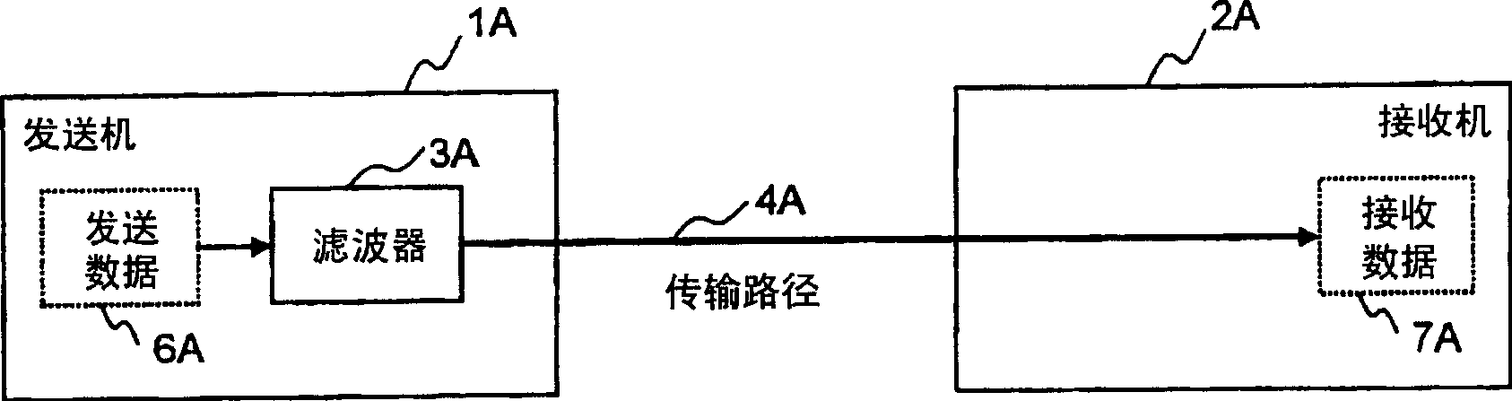
[0032] figure 1 It is a figure explaining the signal transmission system using the transversal filter of this invention.

[0033] The transmitter 1A and the receiver 2A are connected by a transmission path 4A. The transmitter 1A transmits the transmission data 6A to the receiver 2A through the transmission path. The receiver 2A receives this as received data 7A.

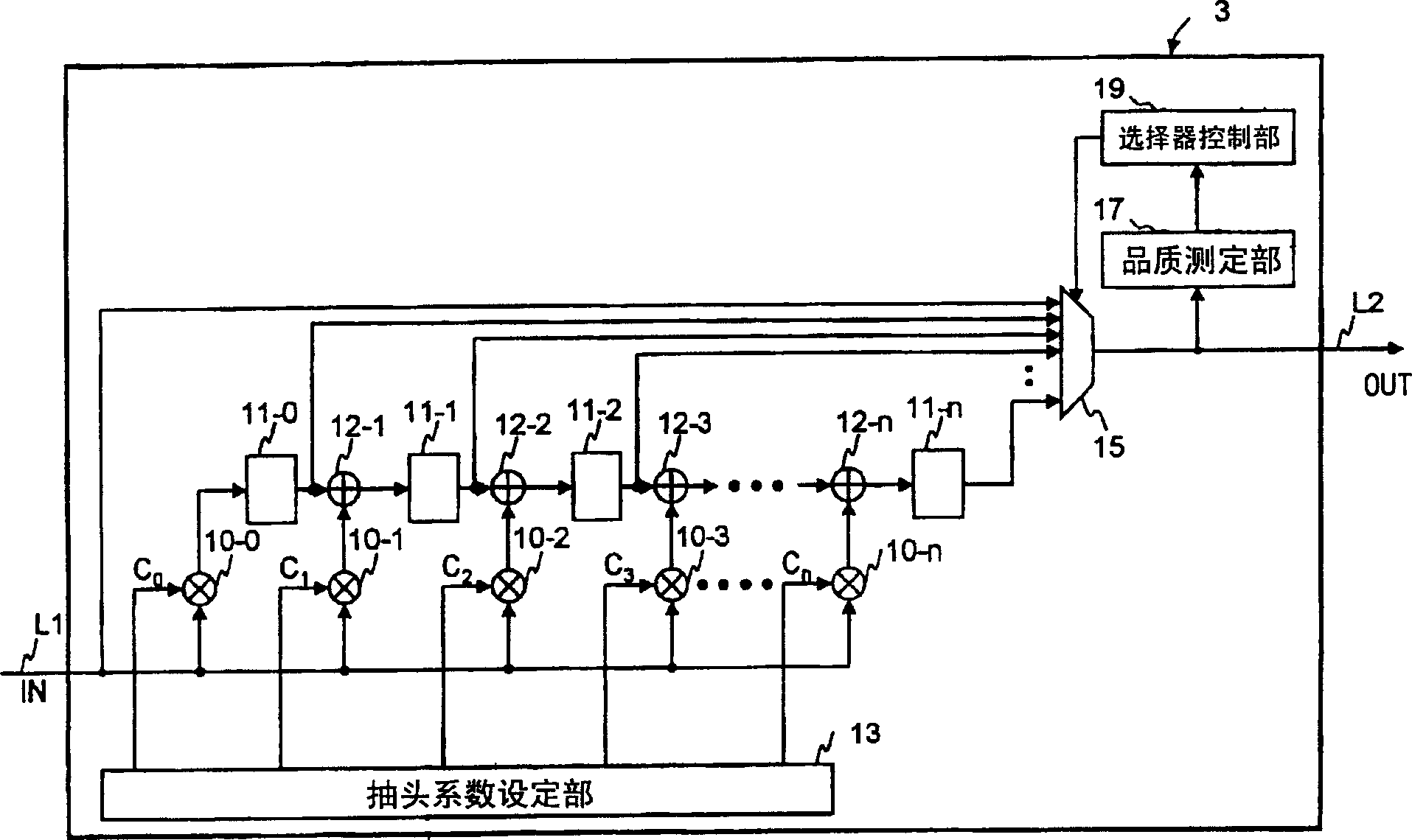
[0034] The transmitter 1A includes a filter 3A. The filter 3A consists of figure 2 The transversal filter configuration explained in .

[0035] The filter 3A enhances the transmission data 6A to be the optimal signal in the frequency response characteristic C(f) of the transmission path, and the optimal signal at the time when the receiver 2A receives the signal, and transmits it to the transmission path.

[0036] The transmitter 1A and the receiver 2A are used for, for example, a network interface inc...


PUM


Abstract

Provided is a transversal filter, in which delayers and multipliers are connected in series, includes: a first multiplier for multiplying a first tap coefficient set by a tap coefficient register module and an input signal to output a result of multiplication; a first delayer for delaying the value output from the first multiplier by a predetermined time to output the delayed value; a second multiplier for multiplying a second tap coefficient set by the tap coefficient register module and an input signal to output a result of multiplication; a first adder for adding the value output from the delayer situated upstream to the value output from the second multiplier to output a result of addition; a second delayer for delaying the value output from the first adder by a predetermined time to output the delayed value; and a selector for selecting one of the input signal, the value output from the first delayer, and the value output from the second delayer to output the selected one.

Description

technical field [0001] The present invention relates to a transversal filter that can improve characteristics degraded on a communication path, and more particularly, to a transversal filter that generates a signal conforming to the characteristics of the communication path and can minimize processing time. Background technique [0002] To transmit signals between two devices, conductor-based electrical communication paths and optical communication paths such as optical fibers are used. This communication path, generally speaking, has a certain bandwidth W (Hz), and if this communication path is used to transmit a signal, the transmitted signal is attenuated by the limitation of the bandwidth W of this communication path. Therefore, this communication path, in the frequency range represented by |f|>W (f is the frequency), is modeled as a linear filter having an equivalent low-pass characteristic with zero attenuation. [0003] Also, such a communication path having a ban...

Claims


Application Information

Patent Timeline
Patent Type & Authority Applications(China)
IPC IPC(8): H03H15/00H04L25/03
CPCH03H17/06H03H17/0294H03H2220/08H04B3/10
Inventor 丰田英弘
Owner HITACHI LTD
Why Eureka
Try Eureka