Camera module

A camera and support member technology, which is applied to cameras, camera bodies, instruments, etc., can solve the problems of long operation time, long hardening time, rising cost, etc., and achieve the effect of increased fixing strength and stable fixing strength.

Inactive Publication Date: 2006-11-29
SMK CO LTD
View PDF2 Cites 7 Cited by
  • Summary
  • Abstract
  • Description
  • Claims
  • Application Information

AI Technical Summary

Problems solved by technology

[0006] However, in the past, in order to fix the cylinder 107 and the base 113, a thermosetting adhesive was used as the adhesive injected into the screw part 115, so the hardening time was long (for example, 30 minutes to 60 minutes), and the working time was long. lead to higher costs

Method used


Image

  • Camera module
  • Camera module
  • Camera module

Examples


Embodiment Construction

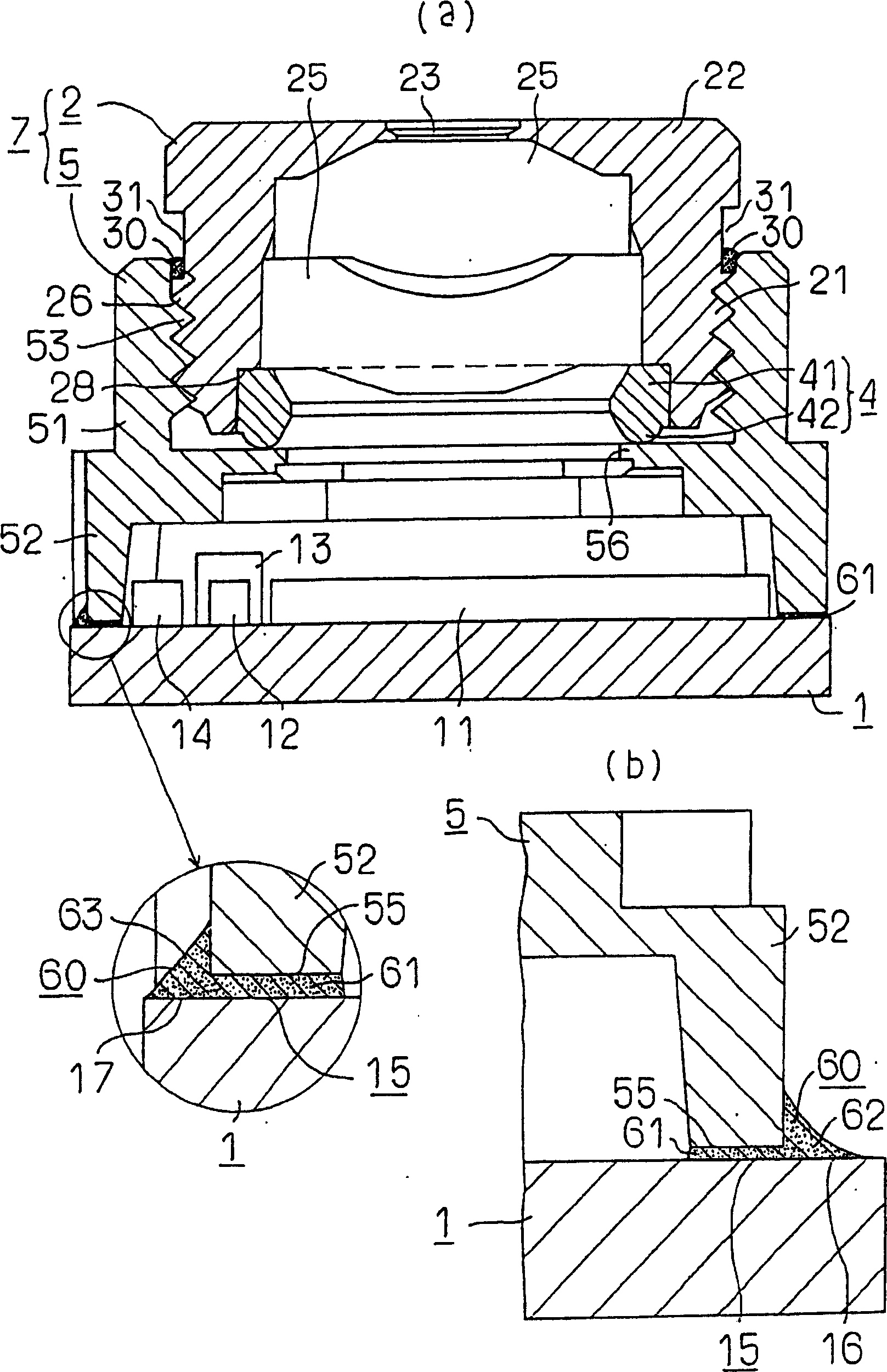
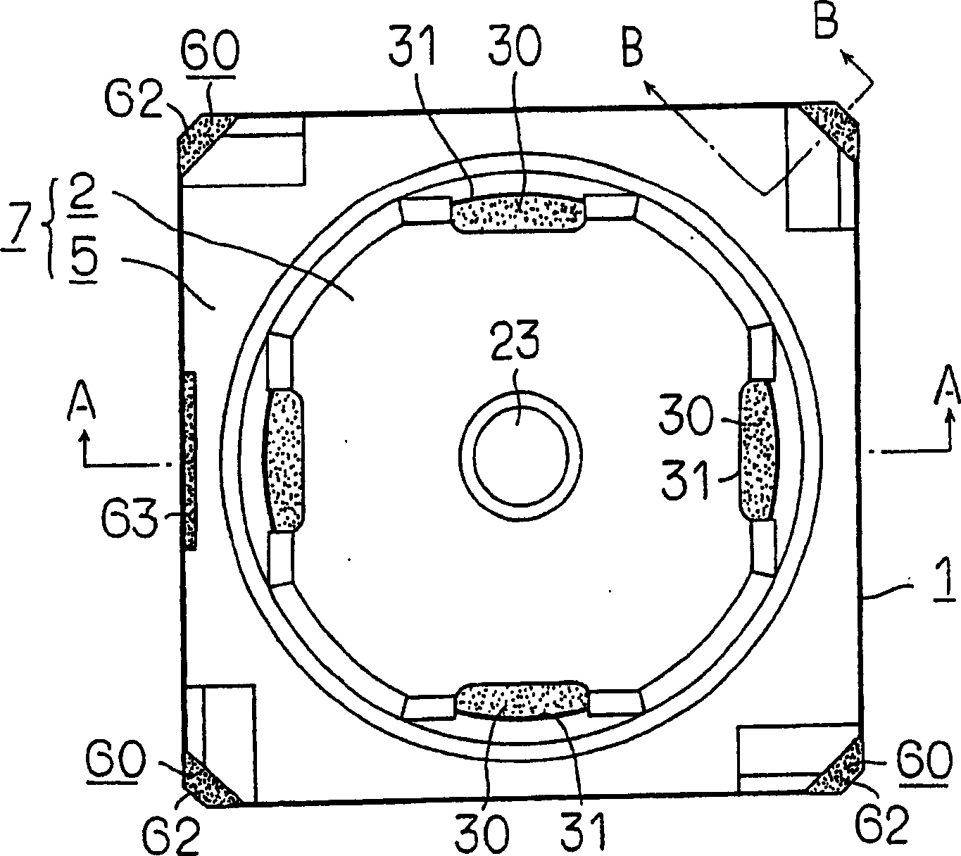
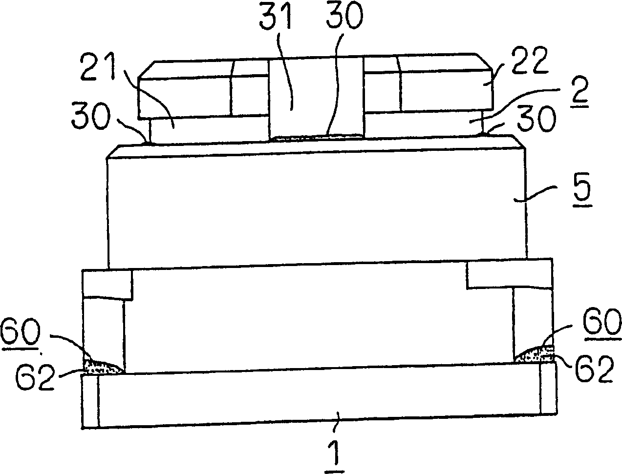
[0032] Figure 1 to Figure 8 An embodiment of the present invention is shown. In these figures, reference numeral 1 is a circuit board (hereinafter referred to as a substrate), reference numeral 2 is a cylinder as an example of a first support member, and reference numeral 4 is an annular elastic body as an example of an elastic member. , Reference numeral 5 is a base as an example of the second supporting member.

[0033] The cylinder 2 and the base 5 support the lenses 25 , 25 and form a support member 7 fixed on the substrate 1 .

[0034] Substrate 1 as Figure 7 As shown in (b), it is formed into a substantially square plate shape with synthetic resin, and is formed into a shape with four corners cut off.

[0035] In the upper central part of the substrate 1, such as figure 1 As shown in (a), the imaging element 11 and other circuit elements 12 to 14, etc., which are electrically connected by a wiring pattern (not shown), are arranged, and external connections are arra...


PUM


Abstract

Here is a kind of camera module whose cylinder (2) is screw joint with the base (5) fixed on the base plate (1), and adjust lenses' (25,25) focusing distance can be adjusted by changing screwing. Dent (31) bestriding the cylinder (2) and the base (5) is formed on at least one of them and can receive extra light, and by injecting photohardening adhesive (30) into the dent (31), the cylinder (2) and the base (5) can be fixed. The photohardening adhesive (30) can vulcanize in a short time and has so high viscosity that it will not immerge into the screwing part between the cylinder (2) and the base (5). This invention can cut the time for fixing the cylinder (2) and the base (5); thereby work time and cost are cut down.

Description

technical field [0001] The present invention relates to a camera module used in a mobile phone, a portable terminal, and the like. Background technique [0002] Conventional camera modules such as Figure 9 As shown, it is equipped with: a circuit board (hereinafter simply referred to as a substrate) 103 equipped with an imaging element 101, a cylinder 107 supporting the lenses 105, 105, and a cylinder 107 screwed to the cylinder 107 and an adhesive 109 , 111 are fixed on the base 113 on the base plate 103, and adjust the distance between the lenses 105, 105 and the imaging element 101 (that is, the focal length of the lenses 105, 105) by adjusting the screwing amount of the cylinder 107 and the base 113 (for example, refer to Patent Document 1). [0003] The adjusted fixing between the cylinder 107 and the base 113 is performed, for example, by injecting an adhesive into the screwing portion 115 between the cylinder 107 and the base 113 (for example, refer to Patent Docume...

Claims


Application Information

Patent Timeline
Patent Type & Authority Applications(China)
IPC IPC(8): H04N5/225G02B7/02H01L27/14
CPCG03B17/561
Inventor 真野伸之
Owner SMK CO LTD
Why Eureka
Try Eureka