
Display

A display and reflective layer technology, applied in instruments, electrical solid-state devices, semiconductor devices, etc., can solve problems such as display brightness decline

Inactive Publication Date: 2006-11-29
TOSHIBA MATSUSHITA DISPLAY TECH
View PDF1 Cites 8 Cited by
  • Summary
  • Abstract
  • Description
  • Claims
  • Application Information

AI Technical Summary

Problems solved by technology

However, in this case the contrast characteristics are improved but the display brightness is reduced

Method used


Image

  • Display
  • Display
  • Display

Examples


Embodiment Construction

[0034] A display according to an embodiment of the present invention will now be described with reference to the accompanying drawings. In this embodiment, as an example of a display, a self-luminous display such as an organic EL (Electro Luminescence) display is described.

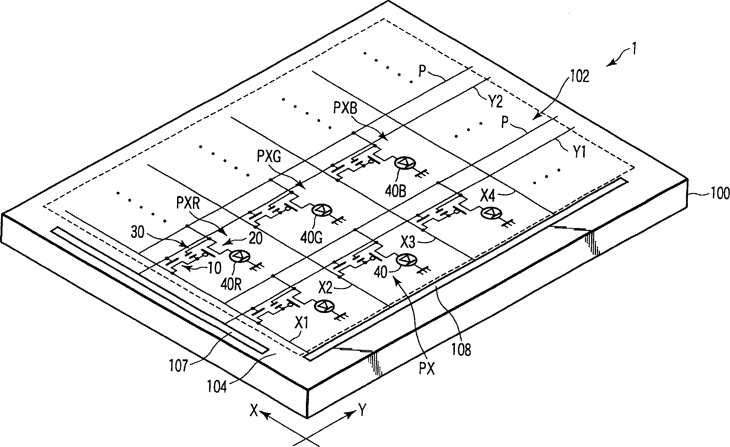
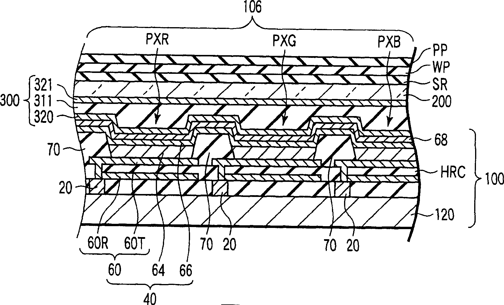
[0035] Such as figure 1 with 2 As shown, the organic EL display 1 is configured to have: an array substrate 100 having a display area 102 for displaying an image; and a sealing member 200 for sealing at least the display area 102 of the array substrate 100 . The display area 102 of the array substrate 100 includes a plurality of pixels PX (R, G, B) arranged in a matrix.

[0036] Each pixel PX (R, G, B) includes: a pixel switch 10, whose function is to electrically separate the on-state pixel from the off-state pixel and retain the video signal on the on-state pixel; The video signal supplied by the switch 10 supplies a desired drive current to the associated display element; and the storage capacitor e...


PUM


Abstract

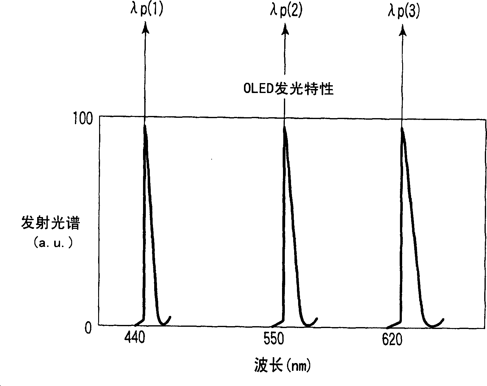
A display characterized in that it comprises a selective reflecting layer (SR) provided between a quarter-wave plate (WP) and a light-emitting layer (64), containing liquid crystal molecules aligned at predetermined helical pitches, transmitting a first circularly polarized light, and selectively reflecting a second circularly polarized light having a polarity opposite to that of the first circularly polarized light and a predetermined wavelength, the light-emitting layer (64) has at least one peak wavelength, the selective reflecting layer (SR) has m selective reflection wavelength regions when the number of peak wavelengths of the light-emitting layer (64) is m, the peak wavelength lambdap(k) of the light emitted from the light-emitting layer (64) (where k=1, 2, ..., m in the descending order of wavelength) is smaller than the product ne(k)P(k) of the extraordinary light refractive index ne(k) of the selective reflecting layer (SR) constituting the selective reflection wavelength regions and the helical pitch P(k) and larger than the product no(k)P(k) of the ordinary light reflective index no(k) and the helical pitch P(k), and the condition ne(k-1)P(k-1)<no(k)P(k) is satisfied between the selective reflecting layers (SR) constituting the selective reflection wavelength regions.

Description

technical field [0001] The invention relates to a display, in particular to a display comprising a circular polarizing plate capable of realizing high contrast and a self-luminous element. Background technique [0002] In recent years, organic electroluminescent (EL) elements have attracted special attention as a typical self-luminescent element that can be included in displays because organic light-emitting materials applied to organic EL elements have been developed to practical level, and organic EL elements have features such as low power consumption, wide viewing angle, small thickness, and light weight. [0003] A general organic EL element is configured such that a light emitting layer is sandwiched between a first electrode (which mainly has light reflection) and a second electrode (which mainly has light transmission). In the organic EL element having such a structure, light generated from the light emitting layer is extracted from the second electrode side. Speci...

Claims


Application Information

Patent Timeline
Patent Type & Authority Applications(China)
IPC IPC(8): G09F9/00G09F9/30H05B33/12H01L27/32H01L51/52
CPCH01L27/3244H01L51/5237H01L51/5281H10K59/12H10K50/846H10K50/8426H10K50/86H05B33/22H05B33/24
Inventor 久武雄三
Owner TOSHIBA MATSUSHITA DISPLAY TECH
Learn More