Method and equipment for triggering protection of optical network under shared configuration of receiving devices

A technology of receiving equipment and optical network, applied in the field of optical communication, can solve the problems of unavoidable system error operation, inability to effectively discriminate the recovery signal and the working channel repaired recovery signal, etc., to achieve the effect of avoiding erroneous operation

Active Publication Date: 2006-12-06
ZTE CORP
View PDF0 Cites 34 Cited by
  • Summary
  • Abstract
  • Description
  • Claims
  • Application Information

AI Technical Summary

Problems solved by technology

[0003] The technical problem to be solved by the present invention is to provide a method and device for triggering optical network protection under the shared configuration of receiving equipment, so as to solve the problem that the existing technology cannot effectively distinguish the recovery signal caused by switching and the recovery signal caused by the repair of the working path. Technical problems to avoid erroneous operation of the system

Method used


Image

  • Method and equipment for triggering protection of optical network under shared configuration of receiving devices
  • Method and equipment for triggering protection of optical network under shared configuration of receiving devices
  • Method and equipment for triggering protection of optical network under shared configuration of receiving devices

Examples


Embodiment Construction

[0030] The specific technical implementation of the present invention will be described in detail below in conjunction with the accompanying drawings and application examples.

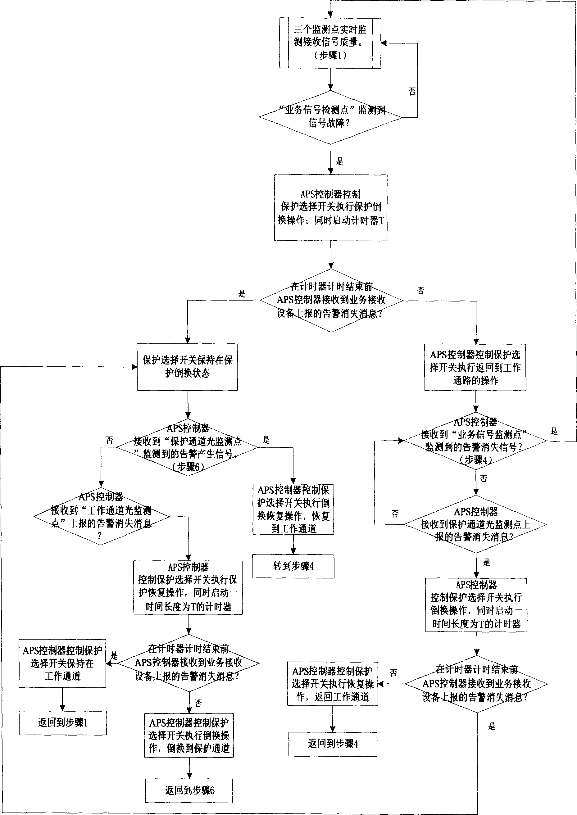
[0031] The present invention proposes a corresponding solution to the problem of reliable triggering of system protection switching under the application situation of shared receiving equipment configuration, image 3 Trigger flow chart for shared receiving device protection, as shown in the figure, mainly includes the following implementation steps:

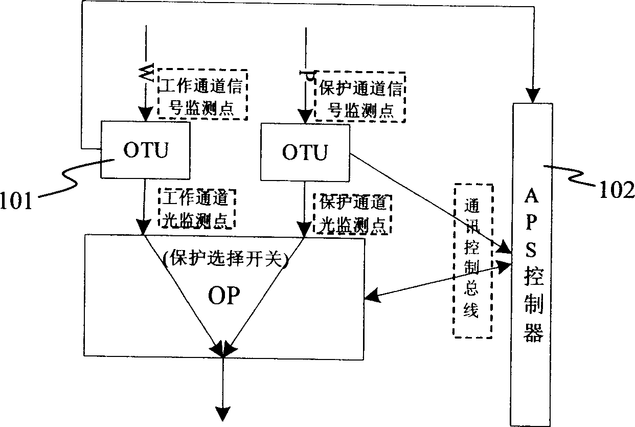
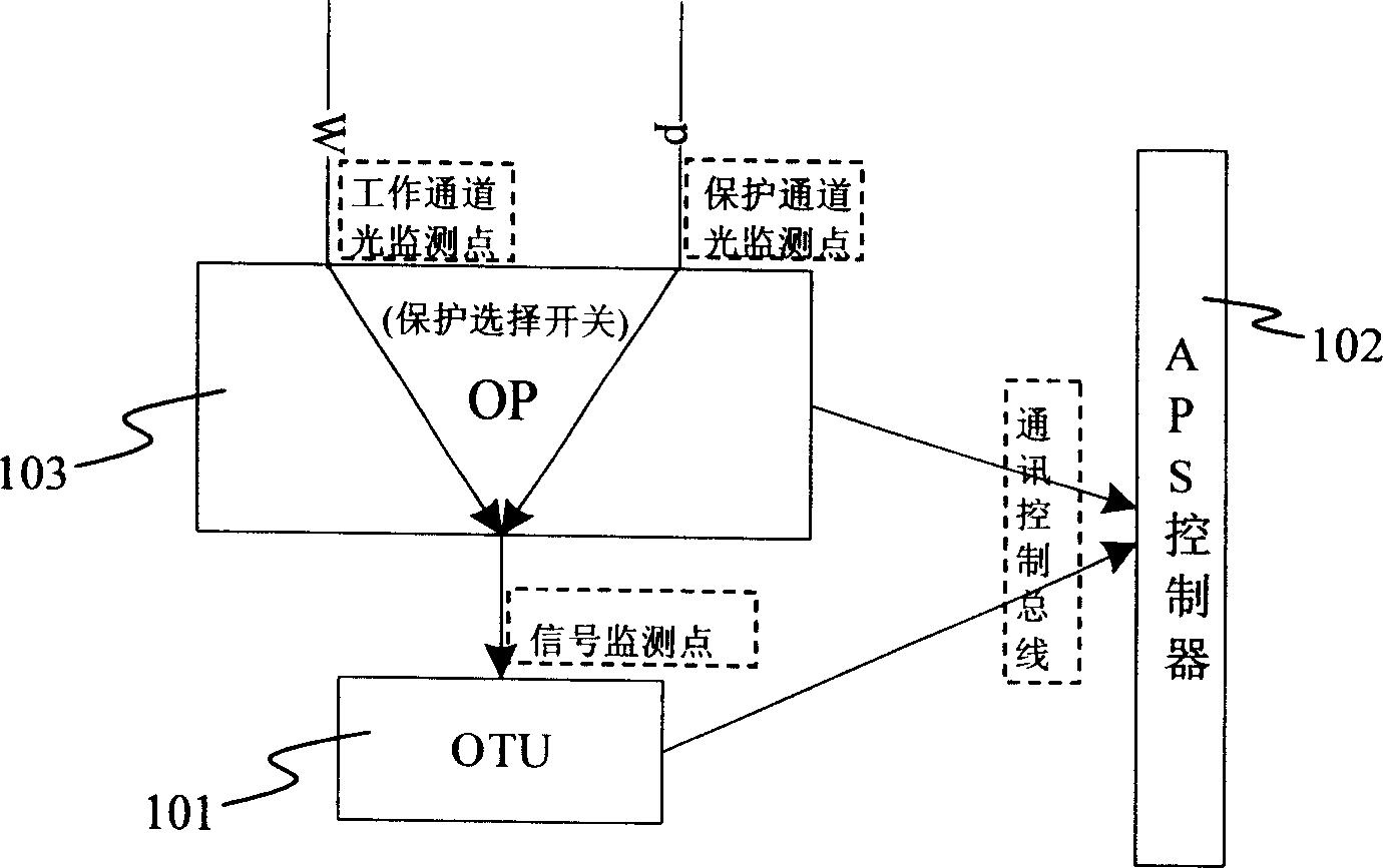
[0032] 1) First, it is necessary to comprehensively share the trigger information of each detection point that the protection device can provide, figure 2 The shown device can provide the following three detection points: a service signal detection point, a working channel optical detection point, and a protection channel optical detection point.

[0033]2) When the "service signal detection point" detects a signal failure, the OTU sends an APS trigger...


PUM


Abstract

The method includes steps: selecting single board to connect working channel or protected channel to equipment of receiving service; based on detected results from light check point in working channel, light check point in protected channel, and check point of service signal of the receiving equipment, automatic protecting rearrangement controller determines whether fault in working channel and protected channel occurs. Moreover, the controller controls the selected single board to carry out switching according to following modes: if working channel is good, then switch is retained at the working channel; if working channel is in fault, and protected channel is good, then switch is retained at the protected channel; if both of working channel and protected channel are in fault, then switch is retained at working channel. The invention can determine restoring signals caused by rearrangement, and caused by restored working channel effectively so as to avoid error operation of system.

Description

technical field [0001] The invention relates to the field of optical communication, in particular to the realization technology of optical transmission network protection switching using WDM (Wavelength Division Multiplexing) technology. Background technique [0002] In the current application of optical transport network protection switching, there are two system configuration methods for the receiving equipment of the protected service signal: redundant configuration of receiving equipment and shared configuration of receiving equipment, respectively as follows figure 1 and figure 2 shown. for figure 1 In the redundant configuration mode of the receiving device shown, a service signal receiving device 101 is configured on each of the working path and the protection path, which can detect the quality of the service signal on the path where it is located. Switching) The controller 102 (used to implement the APS protocol algorithm processing function) provides trigger sig...

Claims


Application Information

Patent Timeline
Patent Type & Authority Applications(China)
IPC IPC(8): H04B10/17
CPCH04Q2011/0081H04Q11/0062
Inventor 王振宇
Owner ZTE CORP
Why Eureka
Try Eureka