Method for recognizing failure node in network

A network node and fault node technology, applied in the field of communication, can solve the problems of difficult maintenance, affecting network security, increasing investment costs, etc., to achieve the effect of speeding up fault location, improving identification efficiency, and reducing maintenance costs

Inactive Publication Date: 2006-12-06
HUAWEI TECH CO LTD
View PDF0 Cites 16 Cited by
  • Summary
  • Abstract
  • Description
  • Claims
  • Application Information

AI Technical Summary

Problems solved by technology

[0005] 1. In the existing technology, technicians in the computer room need to manually check the fault nodes, so the efficiency is low, the response to faults is slow, and the personnel on duty are required to have corresponding technical knowledge, and the maintenance is relatively difficult
[0006] 2. The existing technology needs to be equipped with additional dedicated network detection equipment, thus increasing the investment cost, and at the same time requires complex configuration on the detection equipment, which will affect network security

Method used


Image

  • Method for recognizing failure node in network
  • Method for recognizing failure node in network
  • Method for recognizing failure node in network

Examples


no. 1 example

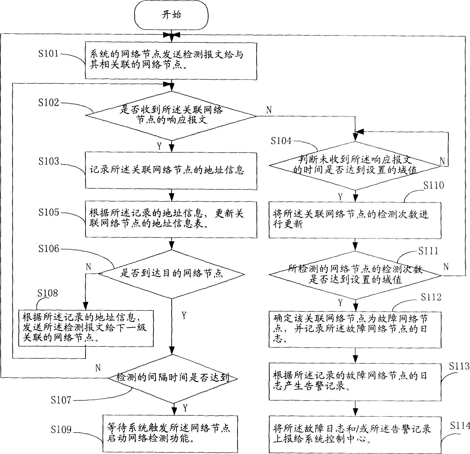
[0046] The first embodiment provided by the present invention, such as figure 1 shown, including:

[0047] In step S101, a network node of the system sends a detection message to its associated network node.

[0048] Step S102, judging whether a response message from the associated network node is received, if yes, execute step S103; if not, execute step S104.

[0049] Step S103, record the address information of the associated network node, and then execute step S105.

[0050] Step S105, updating the address information table of the associated network node according to the recorded address information.

[0051] Step S106, judging whether the destination network node is reached, if yes, execute step S107; otherwise, execute step S108.

[0052] Step S107, judge whether the detection interval time has been reached, if so, continue to execute step S101; otherwise, execute step S109, that is, wait for the system to trigger the network node to start the network detection functio...


PUM


Abstract

Core of the method is as following: first, network node of system sends detection message to other associated network nodes; then, monitoring response messages from the said associated network nodes; if verifying that response message from an associated network node is not received then the method determines the associated network node is a fault network node. Without need of preparing additional special network detection device, and without need of debugging fault nodes through manual work by technicians, the invention can position network fault accurately, and quicken speed for positioning fault. Advantages are: increasing efficiency of recognizing fault point of network, reducing maintenance cost of system, raising degree of satisfaction of users, and not influence on safety of network.

Description

technical field [0001] The invention relates to the field of communication, in particular to a method for identifying network failure nodes. Background technique [0002] Under the current NGN (Next Generation Network; next-generation network) architecture, services are based on IP networks, and the stability of the bearer network directly affects the stability of NGN applications. Therefore, rapid location of network faults and automatic identification of faulty nodes will greatly Reduce maintenance burden and reduce maintenance cost. [0003] The technical solution of the prior art 1 related to the present invention is: first configure additional dedicated network fault detection equipment, when the network fails, the equipment room technicians manually check the bearer network equipment segment by section through the dedicated detection equipment, Until the faulty node is confirmed. [0004] As can be seen from the technical solutions of the prior art, it has the follow...

Claims


Application Information

Patent Timeline
Patent Type & Authority Applications(China)
IPC IPC(8): H04L12/26
Inventor 杨波何理想
Owner HUAWEI TECH CO LTD
Why Eureka
Try Eureka