
Method of signal scheduling synchronization and synchronization circuit

A timing synchronization, signal technology, applied in the direction of synchronization signal speed/phase control, channel estimation, electrical components, etc., can solve the problem of confirmation symbol boundary misjudgment, delay and other problems

Active Publication Date: 2006-12-06
VIA TECH INC
View PDF0 Cites 12 Cited by
  • Summary
  • Abstract
  • Description
  • Claims
  • Application Information

AI Technical Summary

Problems solved by technology

[0010] However, since the traditional fine timing synchronization method uses two long training symbols to calculate the output value of the matched filter, it causes delays in subsequent procedures such as fast Fourier transform
In addition, in the process of calculating the output value of the matched filter, because the peak point is to be found to determine the symbol boundary, the peak point is often confused with the pre-peak point (pre-peak) that appears in front of it, resulting in the confirmation of the symbol Misjudgment of the boundary process

Method used


Image

  • Method of signal scheduling synchronization and synchronization circuit
  • Method of signal scheduling synchronization and synchronization circuit
  • Method of signal scheduling synchronization and synchronization circuit

Examples


Embodiment Construction

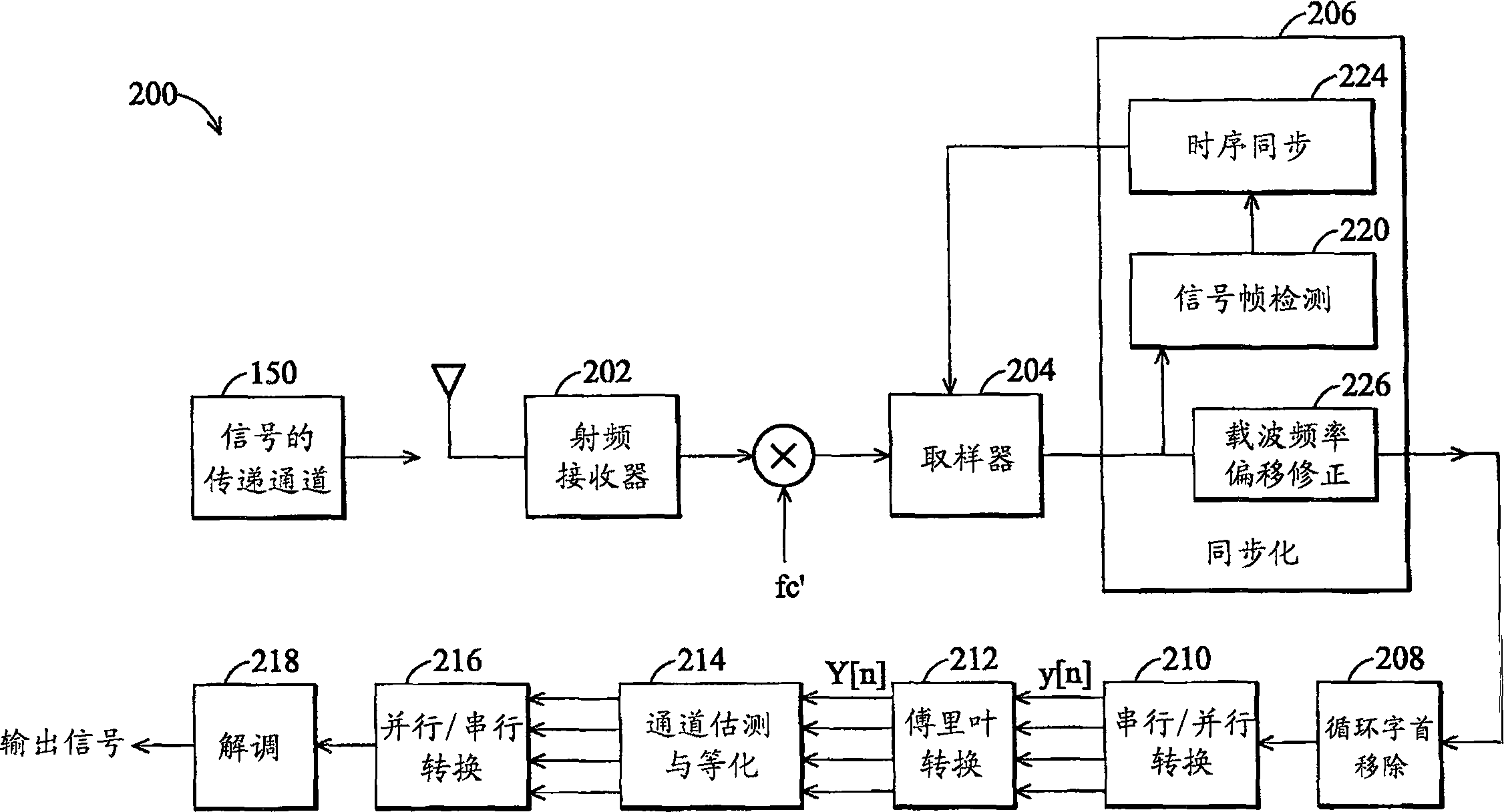
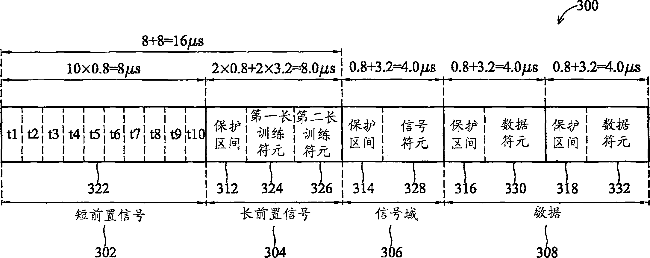
[0056] Figure 4 Shown is a flowchart of a method 400 for fine timing synchronization according to the present invention. The method 400 first performs signal frame detection in step 402 to detect whether a sample signal including OFDM symbols is received. Next, if it is determined that a sample signal containing OFDM symbols is received, try to detect the end of the short preamble within the sample in step 404 . The samples after the end of the short preamble belong to the long preamble, so in step 406 the subsequent samples are sent to a matched filter to generate a series of correlation peaks. In the matched filter, samples are correlated with an ideal long training symbol to generate correlation peaks. The output signal generated by the matched filter contains correlation peaks, and timing related information can be obtained from the correlation peaks. Step 408 searches for a first maximum peak point with a maximum value in a search range of the correlation peak generat...


PUM


Abstract

A method for fine timing synchronization is provided. The method comprises: detecting an end point of the short preamble; delivering the samples after the end point to a matched filter to generate a plurality of correlation peaks; searching the correlation peaks generated from the samples of the first LTS for a first maximal peak point which is the correlation peak with a first maximal intensity, and obtaining the first time index of the first maximal peak point; searching the correlation peaks generated from the samples of the first LTS for a pre-peak point which is the correlation peak forming a peak intensity appearing before and nearest to the first maximal peak point, and obtaining the second time index of the pre-peak point; estimating a third time index of the start point of the second LTS according to the first and second time indexes.

Description

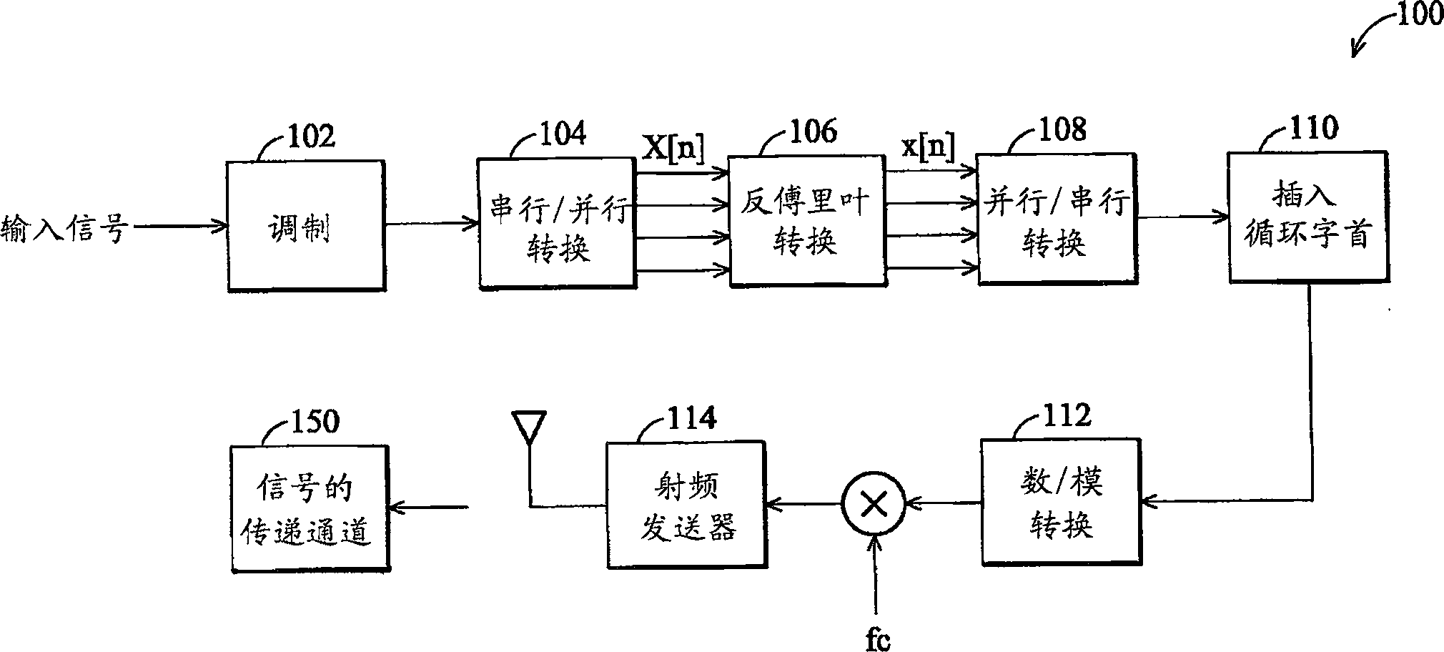
technical field [0001] The present invention relates to an Orthogonal Frequency Division Multiplexing (OFDM) system, in particular to an Orthogonal Frequency Division Multiplexing baseband receiver (baseband receiver) conforming to IEEE 802.11a or IEEE 802.11g standards. Background technique [0002] Orthogonal Frequency Division Multiplexing (OFDM) is a modulation technique used in wireless networks conforming to standards such as IEEE 802.11a or 802.11g. OFDM disperses data on several sub-carriers for transmission, and each sub-carrier is separated from each other by a certain frequency. Due to the orthogonality of the data transmitted on the sub-carriers, they will not interfere with each other. Since the data is distributed and transmitted, the time available for transmitting data symbols on each carrier is extended, thereby reducing inter symbol interference. Therefore, OFDM technology is popular in communication systems with high bit transmission rates. [0003] In ...

Claims


Application Information

Patent Timeline
IPC IPC(8): H04L27/26H04L7/08
CPCH04L27/261H04L25/022H04L27/2675H04L27/2656
Inventor 高凯鹏
Owner VIA TECH INC
Learn More