Device for automatically injecting liquids to be injected

An automatic injection and injection technology, applied in the direction of automatic injectors, syringes, ampoule syringes, etc., can solve problems such as hindering the rapid introduction of injections, not fully meeting actual requirements, blocking injection needles, etc.

Active Publication Date: 2006-12-06
药品咨询有限责任两合公司
View PDF2 Cites 20 Cited by
  • Summary
  • Abstract
  • Description
  • Claims
  • Application Information

AI Technical Summary

Problems solved by technology

The disadvantage of this known design is that the ruptured membrane blocks the injection needle and prevents the quick release of the injection
[0005] How

Method used


Image

  • Device for automatically injecting liquids to be injected
  • Device for automatically injecting liquids to be injected
  • Device for automatically injecting liquids to be injected

Examples


Embodiment Construction

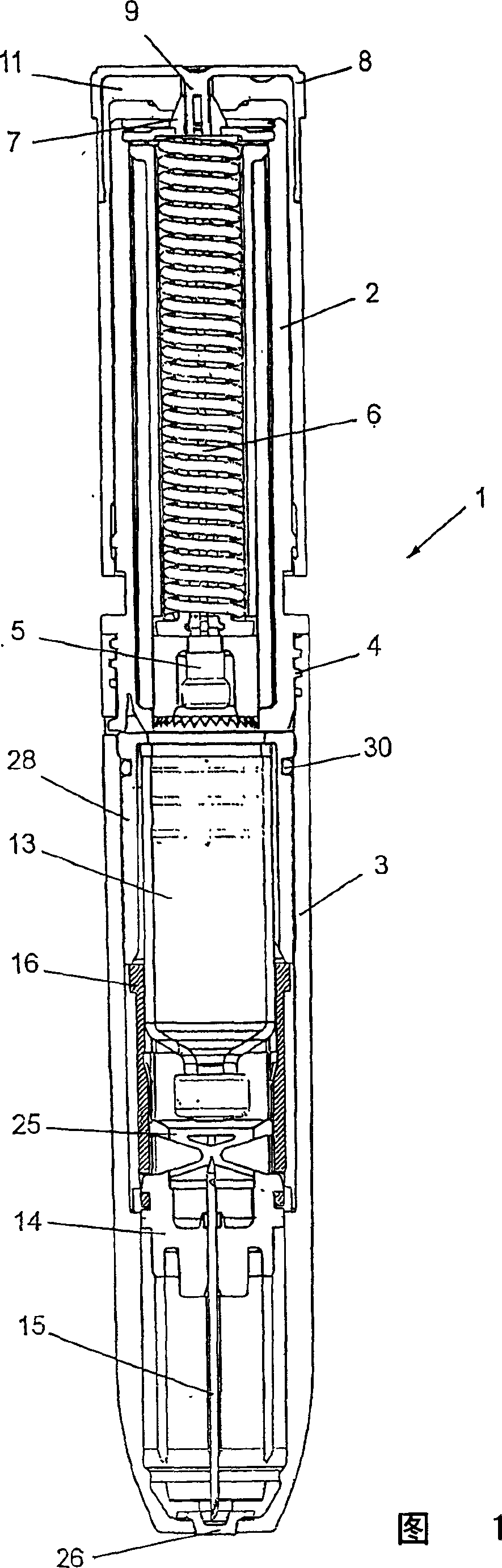
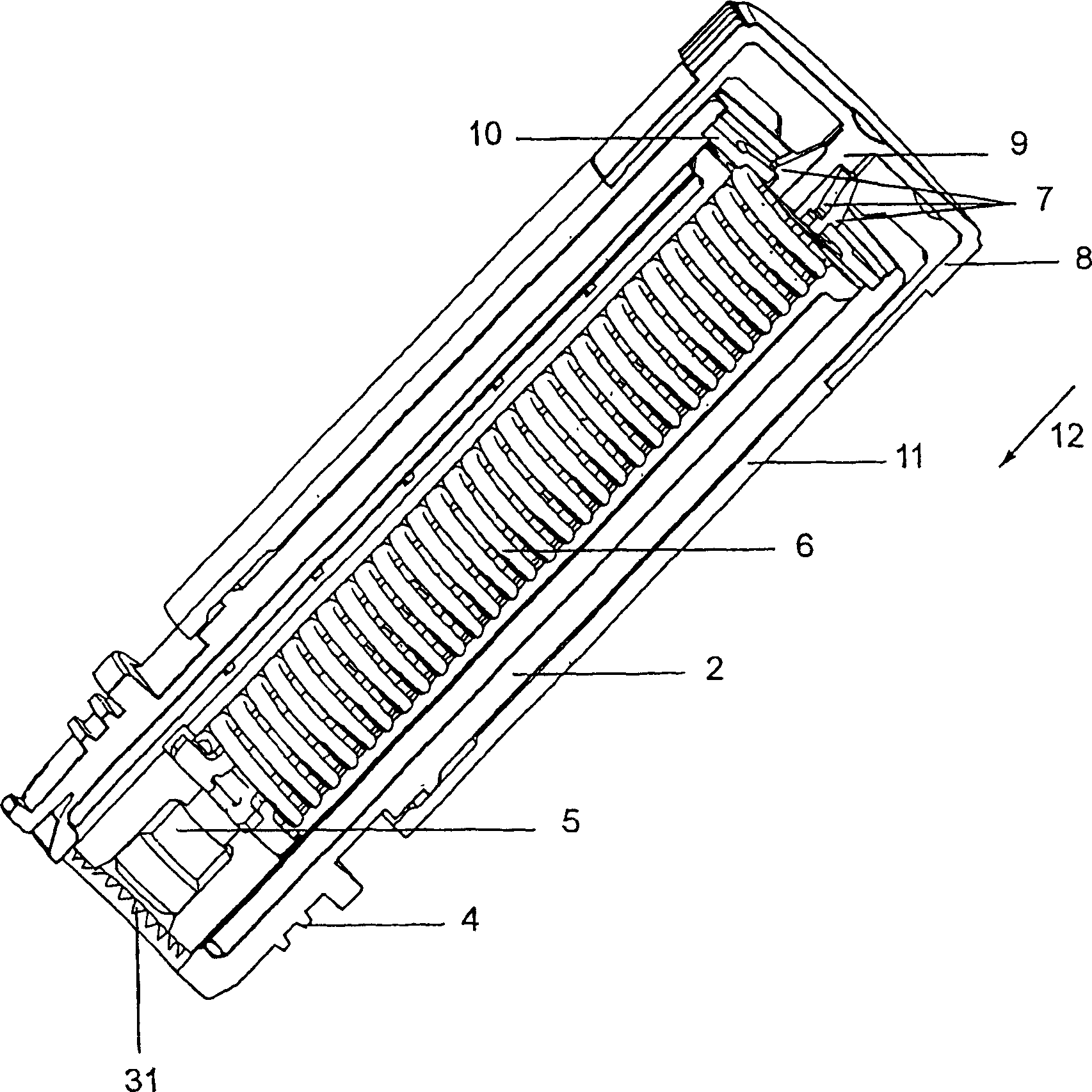
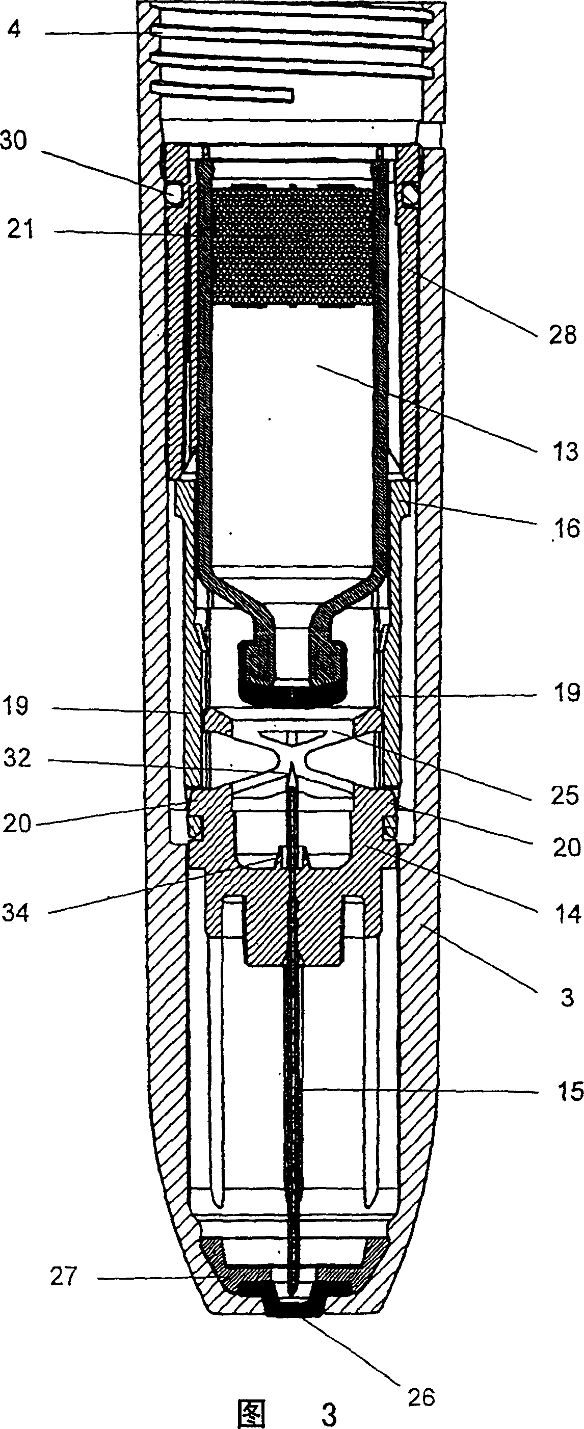
[0014] FIG. 1 shows an injection device 1 , the housing of which is segmented in the axial direction. The first housing part 2 encloses the actuator part and the second housing part 3 encloses the syringe part of the injection device according to the invention, wherein the two housing parts can be connected by means of a screw thread 4 . exist figure 2 The actuator part shown in detail in includes a pressure bolt 5 which is axially displaceable in the housing 2 and which can be pushed in against a spring 6 . The pressure screw 5 has an inwardly elastic locking shoulder 7 which forms the conical end of the pressure screw 5 . In the locked position, a pin 9 of the cover 8 holds the locking shoulder 7 in a radially outwardly offset position, so that the locking shoulder 7 engages the ring part 10 . After the top cover 8 has been pulled off, the actuator can be partially released. For this reason, the protective sleeve 11 is operated in the direction of the arrow 12, so that the...


PUM


Abstract

The invention relates to an automatic injection device (1) comprising a housing that is sub-divided in the axial direction, the parts of said housing being interconnectable. An axially displaceable stud (5) is guided in a first part (2) of the housing, and an injection canula (15) blocked in a canula guiding mechanism (14) is mounted, with an ampule (13), in the second part (3) of the housing in such a way that they can be displaced in relation to each other. According to the invention, the injection canula (15) is embodied as a puncturing part (32) for the ampule (13), on the side thereof facing the ampule (13), and the end of the ampule (13) facing the injection canula (15) is plunged into a sleeve (16) blocked in the second part (3) of the housing, the inner diameter of the sleeve essentially corresponding to the outer diameter of the ampule (13). Radially inwardly protruding projections (17) are formed on the inner circumference of the sleeve (16), and the sleeve (16) comprises locking elements which co-operate with locking elements (20) of the canula guiding mechanism (14). An axial displacement of the ampule (13) in the direction of the canula guiding mechanism (14), overcoming the displacement resistance exerted by the projections (17), causes the release of the locking elements (20) and the axial displaceability of the canula guiding mechanism (14).

Description

technical field [0001] The invention relates to a device for the automatic injection of injection fluids, which has an axially segmented housing, the segments of which can be connected to each other, wherein an axially axially movable movable pressure bolt, which can be pushed in against the accumulator and can be locked in the pushed-in position, and can be moved out when the accumulator is unloaded; Injection needle and an ampoule in the needle guide, which can be moved axially relative to each other, wherein the injection needle is formed on its side facing the ampoule as a piercer for the ampoule. Background technique [0002] Devices of the type mentioned at the outset are widely known by the name of autoinjectors. Known devices of this type are devices which, in the event of an emergency, make it easier to inject emergency medication into the body. Auto-injectors are used eg in allergic emergencies such as insect stings, snake bites etc., but also in the military fie...

Claims


Application Information

Patent Timeline
IPC IPC(8): A61M5/20A61M5/24A61M5/31A61M5/32
CPCA61M5/3287A61M2005/3118A61M5/2033A61M5/2466A61M2005/2073A61M2005/2418A61M2005/206
Inventor E·皮克哈德
Owner 药品咨询有限责任两合公司
Why Eureka
Try Eureka