Supercharge Your Innovation With Domain-Expert AI Agents!

Sensor arrangement for preventing direct debris impact

A technology of sensors and temperature sensors, which is applied in the direction of temperature measurement of moving fluids, etc., and can solve problems such as damage to sensing elements

Inactive Publication Date: 2006-12-06
HONEYWELL INT INC
View PDF0 Cites 0 Cited by
  • Summary
  • Abstract
  • Description
  • Claims
  • Application Information

AI Technical Summary

Problems solved by technology

Even though the trough arrangement of this known temperature sensor instrument protects the sensing element from large debris impacts, the inventors of the present application have found that smaller debris (such as sand) passing through the gas turbine can cause the sensing element as the debris hits the sensing element. component damage

Method used


Image

  • Sensor arrangement for preventing direct debris impact
  • Sensor arrangement for preventing direct debris impact
  • Sensor arrangement for preventing direct debris impact

Examples


Embodiment Construction

[0016] In one aspect, the invention is a temperature sensor device designed to allow air to flow to the temperature sensing element through a series of channels within the housing, thereby preventing / mitigating the effects of debris striking the sensor. Further aspects of the invention will become apparent from the following description with reference to the accompanying drawings.

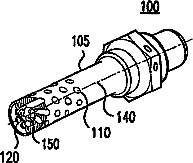
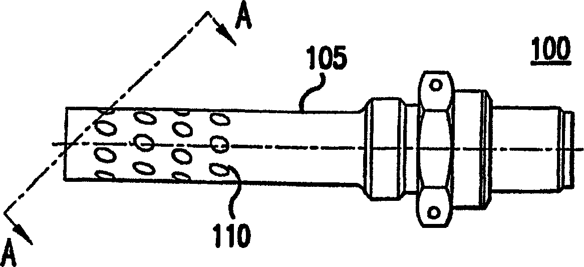
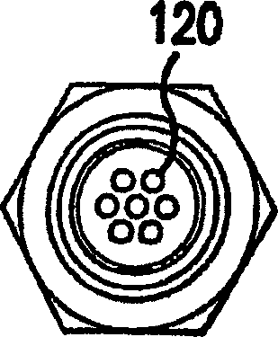
[0017] Figures 1A-1D The temperature sensor device according to the first embodiment of the present aspect was explained. According to a first embodiment, the temperature sensor device 100 comprises a cylindrical housing 105 with an opening structure (hole in this embodiment) 110 for allowing incoming air to flow to a temperature sensor element positioned along a centerline 140 in a cavity 150 .

[0018] The temperature sensor element 100 of the first embodiment may be used in an air channel so that it is positioned with the housing substantially perpendicular to the air flow. In this manner, th...


PUM


Abstract

A temperature sensor arrangement (100, 300) includes a sensor cavity (150), a temperature sensing element (330) being positioned along a center line (140, 340) of the sensor cavity (150) and generating a signal indicating temperature of air flowing thereto, and a generally cylindrical outer casing (105, 305) surrounding the sensor cavity (150). In one embodiment, the outer casing (105) includes a pattern of flow passages (110) for allowing air flow to the temperature sensing element (330) in the sensor cavity (150), the flow passages (110) being angled such that there is no direct line of air flow from an exterior of the outer casing (105) to the sensing element (330). In another embodiment, the flow passages (310) are arranged in an offset pattern relative to a center line (340) of the housing cavity (150), such that there is no direct line of air flow from an exterior of the outer casing (305) to the sensing element (330). The flow passages prevent airborne debris from directly impacting the temperature sensing element.

Description

[0001] related application [0002] Pursuant to 35 U.S.C. §119(e), this application claims priority to U.S. Provisional Application 60 / 514,688, filed October 28, 2003, the entire contents of which are incorporated herein by reference. technical field [0003] The present invention relates to temperature sensors and, more particularly, to a temperature sensor device wherein the sensor housing has an air flow tube structure configured to allow airflow to the temperature sensing element while preventing airborne debris Direct impact on the temperature sensing element. Background technique [0004] Known temperature sensor devices measure the temperature of the air flowing into the channel and comprise a generally cylindrical housing with a cavity in which the sensing element is positioned along the centreline. The housing of one known sensor device includes a slot carved in the centerline to allow air to flow into the sensing element. One implementation of such known temperat...

Claims


Application Information

Patent Timeline
IPC IPC(8): G01K13/02G01K13/024
Inventor P·安德逊P·J·凯恩斯T·J·利波尔德R·R·桑格尔
Owner HONEYWELL INT INC
Features
  • R&D
  • Intellectual Property
  • Life Sciences
  • Materials
  • Tech Scout
  • Unparalleled Data Quality
  • Higher Quality Content
  • 60% Fewer Hallucinations
Learn More