Elastic interlocking intramedullary nail

An intramedullary nail and elastic technology, which is applied in the field of elastic interlocking intramedullary nails of clinical orthopaedic internal fixation devices, can solve the problems of fracture, delayed union, non-union, etc., and achieves accelerated fracture healing, avoids stress shielding, and prevents bone fractures. The effect of loose formation

Inactive Publication Date: 2006-12-13
王秋霞
View PDF0 Cites 10 Cited by
  • Summary
  • Abstract
  • Description
  • Claims
  • Application Information

AI Technical Summary

Problems solved by technology

However, due to the stress shielding of the intramedullary nail, there will still be proble

Method used


Image

  • Elastic interlocking intramedullary nail
  • Elastic interlocking intramedullary nail

Examples


Embodiment Construction

[0010] Introduce embodiments of the present invention below in conjunction with accompanying drawing:

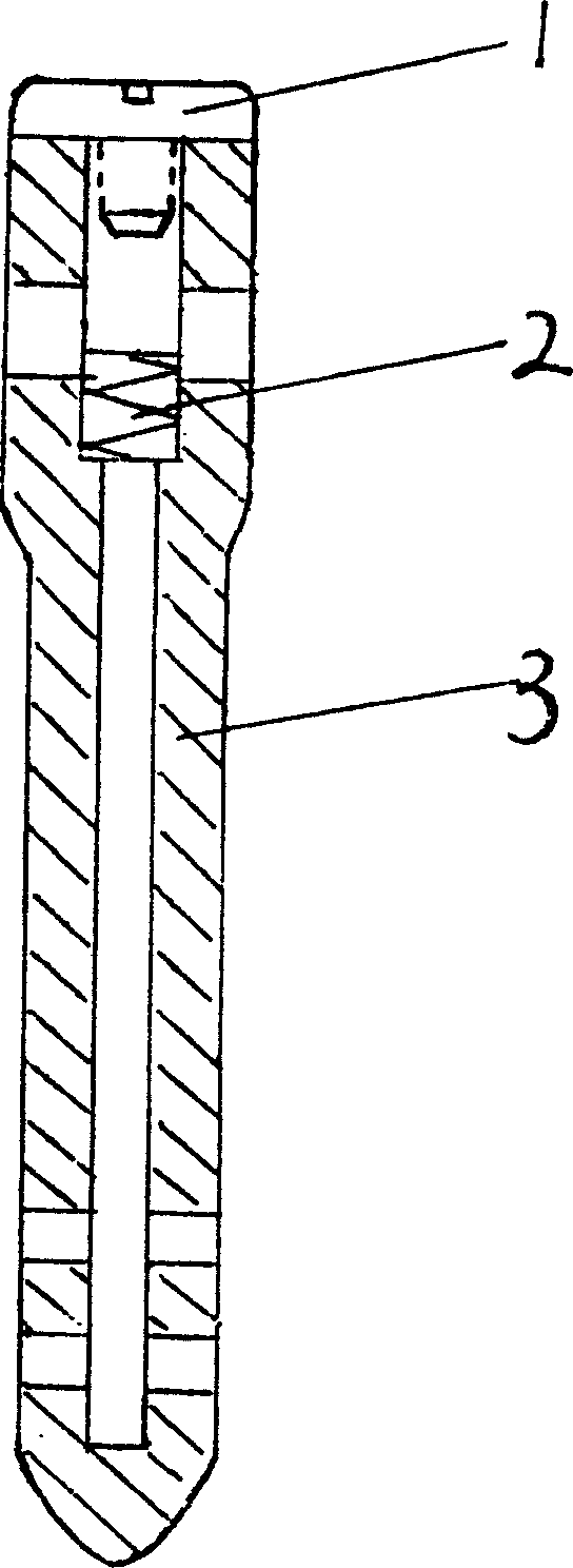
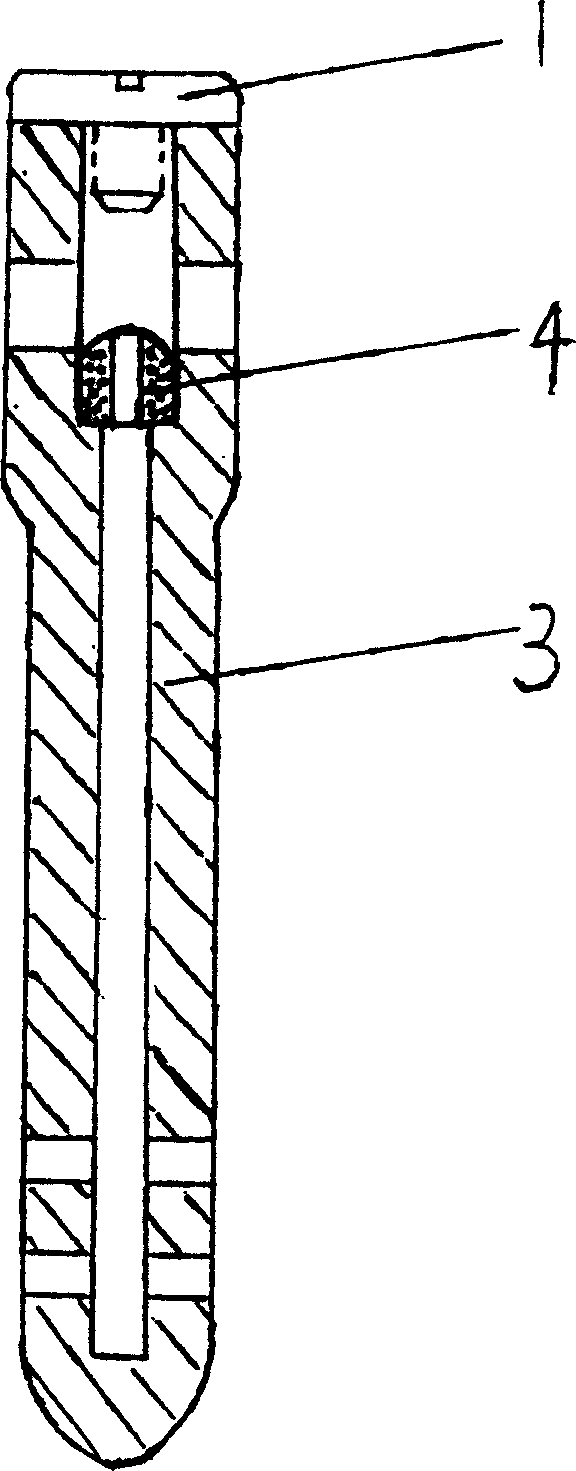
[0011] The elastic interlocking intramedullary nail includes an intramedullary nail and a screw, and the intramedullary nail is composed of a cap screw (1), a nail body (3) and an elastic device (2) (4). Cap screw (1) is threadedly connected with nail body (3). The far and near ends of the nail body (3) are provided with interlocking screw holes, and the axial diameter of the interlocking screw holes at the proximal end of the nail body (3) is slightly larger than the transverse diameter. The inner diameter of the lower edge surface of the elastic device near the cylinder wall is greater than the inner diameter of the lower edge surface far from the cylinder wall, forming a step, the elastic device is located on the step, its upper edge surface is located below the interlocking screw, and the lower edge of the proximal interlocking screw hole is higher than the cylinder Wal...


PUM


Abstract

The invention relates the spring intramedullary nail, comprising intramedullary nail and screw. The intramedullary nail is composed by nail, spring device and cap screw. The cap screw is connected with screw, the axial diameter of screw is more than the transverse diameter of screw, the screw can axially move, in the nail there is steps, the spring device is on the steps, and the spring device is stiff spring or macromolecule elastic capsule. The intramedullary nail has the advantages of improving the acting force of knitting and paresis, accelerating assimilation, enhancing sclerotic strength, and avoiding osteoporosis.

Description

Technical field [0001] The invention relates to an elastic interlocking intramedullary nail, which is a clinical orthopedic internal fixation device, which is suitable for treating bone fractures. Background technique [0002] In the orthopedic treatment of diaphysis fractures, intramedullary nails are usually inserted into the medullary cavity of the diaphysis to connect and fix the fracture ends. With the improvement of fracture internal fixation technology, interlocking intramedullary nails appeared, which effectively controlled the bending, twisting, shearing, and rotating stress of the fracture end, and greatly reduced the rate of fracture nonunion and infection rate. However, due to the stress shielding of the intramedullary nail, there will still be problems such as fracture nonunion, delayed union, or fracture after removal of internal fixation. Contents of the invention [0003] The purpose of the present invention is to solve various difficulties in the existing...

Claims


Application Information

Patent Timeline
IPC IPC(8): A61B17/72
Inventor 王秋霞宋文超裴国献李鉴轶王培
Owner 王秋霞
Why Eureka
Try Eureka