
Apparatus utilizing gravitational potential energy of vehicle running on ramp to generate electricity

A technology of gravitational potential energy and slopes, which is applied in the direction of machines/engines, mechanisms that generate mechanical power, mechanical equipment, etc., can solve the problems of wasting gravitational potential energy and reduce the speed of descent, and achieve the effect of small investment

Inactive Publication Date: 2006-12-13
NORTH CHINA UNIVERSITY OF SCIENCE AND TECHNOLOGY +1
View PDF0 Cites 12 Cited by
  • Summary
  • Abstract
  • Description
  • Claims
  • Application Information

AI Technical Summary

Problems solved by technology

Vehicles going up and down the slope have a large sliding force due to the effect of their gravitational potential energy, especially for vehicles with larger masses. In order to control the sliding speed, braking measures are generally required, that is, to consume gravity. Potential energy to reduce the speed of descent, thereby wasting this gravitational potential energy
How to collect this gravitational potential energy and convert it into useful work has not yet been reported in the literature

Method used


Image

  • Apparatus utilizing gravitational potential energy of vehicle running on ramp to generate electricity
  • Apparatus utilizing gravitational potential energy of vehicle running on ramp to generate electricity
  • Apparatus utilizing gravitational potential energy of vehicle running on ramp to generate electricity

Examples


Embodiment 1

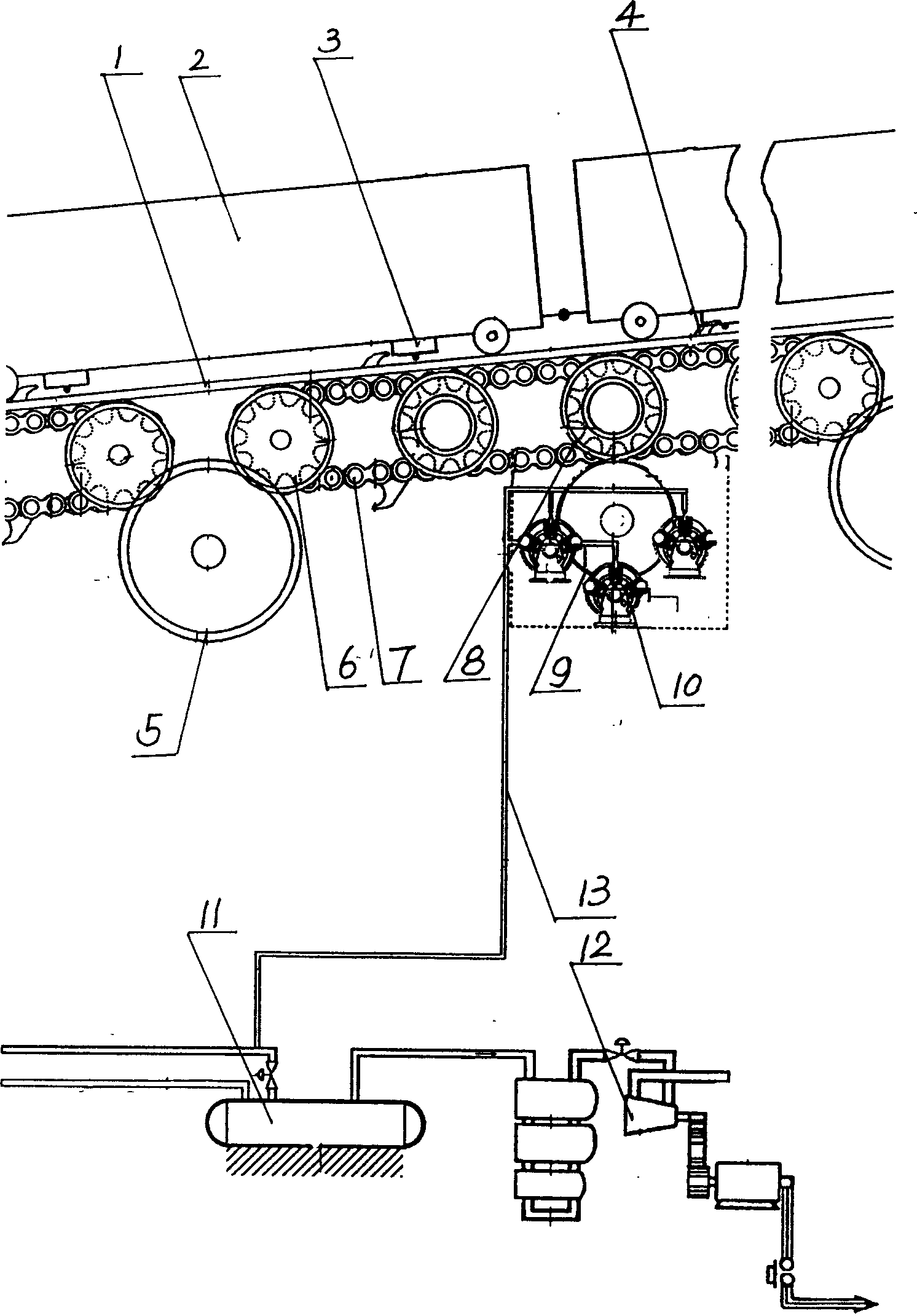
[0012] Embodiment 1 is the present invention that is used on the railway.

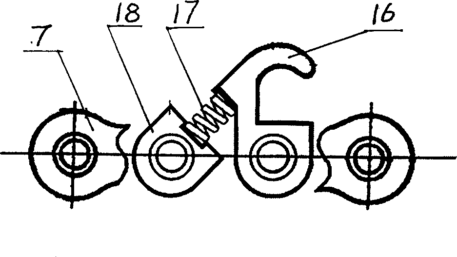
[0013] It consists of an energy releaser 3, an energy absorber 4, an air compressor 10, an air storage tank 11, a gas turbine generator 12, a high-pressure gas pipeline 13, and a mechanical energy exporter. The ramp used to install the power generating device of the present invention is a railway ramp, the ramp angle is greater than 5°, and the mechanical energy exporter is placed under the rail 1 of the railway ramp, and it includes several groups connected in series by gears 5 The sprocket chain transmission device, the chain 7 is equipped with an energy absorber 4, the energy absorber 4 is composed of a hook 16, a spring 17, and a spring seat 18, the hook 16 is hinged with the chain 7, and the spring seat 18 is fixedly connected with the chain 7, and the two are connected by the spring 17; the sprocket 6 is coaxially equipped with a synchronous gear 8, and the synchronous gear 8 is connected to the ...

Embodiment 2

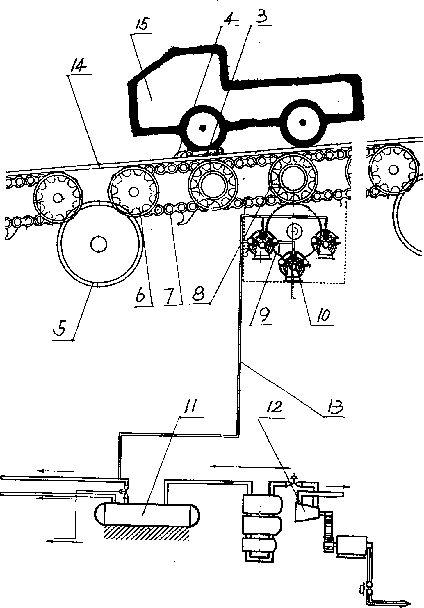
[0015] Embodiment 2 is the present invention that is used on road.

[0016] Similarly, it is also composed of energy releaser 3, energy absorber 4, air compressor 10, gas storage tank 11, gas turbine generator 12, high-pressure gas pipeline 13 and mechanical energy exporter. The ramp used to install the power generating device of the present invention is a road ramp, and the road support slope angle is greater than 10° and less than 30°. The mechanical energy output device is placed under the road ramp through a bridge frame 14, and it includes several groups of gears 5 In the sprocket chain transmission device connected in series, the chain 7 is equipped with an energy absorber 4, the energy absorber 4 is composed of a hook 16, a spring 17, and a spring seat 18, and the hook 16 is hinged with the chain 7, The spring seat 18 is fixedly connected with the chain 7, and the two are connected by the spring 17; The power input gears are meshed, and the air compressor 10, the gas s...


PUM


Abstract

The invention relates to a device for using the gravity of vehicle on slope to generate electricity, which comprises an energy releaser, an energy absorber, an air compressor, an air pot, and a turbine generator. Wherein, the mechanical energy output device is arranged under the slope, which comprises several groups of chain wheel chain transmission devices connected by gear wheels; said chain is mounted with energy absorber matched with the vehicle via energy releaser; said chain wheel is mounted with synchronous gear wheel coaxially, while the gear wheel is meshed to the power input gear wheel of air compressor via medium gear wheel; the air compressor, air pot, and turbine generator are connected via high-pressure air tubes. The invention can absorb the gravity energy of the vehicle on the slope, via the energy absorber, to be transmitted into mechanical energy via the mechanical energy output device, and use compressed air as medium to power the turbine generator, to obtain electricity.

Description

Technical field: [0001] The invention relates to a device for converting gravitational potential energy into electric energy, in particular to a device for generating electricity by utilizing the gravitational potential energy of vehicles running on a slope. Background technique: [0002] Due to geological conditions, in high mountain or hilly areas, railways or highways must be designed with a certain slope. Vehicles going up and down the slope have a large sliding force due to the effect of their gravitational potential energy, especially for vehicles with larger masses. In order to control the sliding speed, braking measures are generally required, that is, to consume gravity. Potential energy is used to reduce the speed of descent, thereby wasting these gravitational potential energies. How to collect this gravitational potential energy and convert it into useful work has not yet been reported in the literature. Invention content: [0003] The object of the present i...

Claims


Application Information

Patent Timeline
Patent Type & Authority Applications(China)
IPC IPC(8): F03G7/08
CPCF03G7/08
Inventor 郭威娜郭基生张庆凌
Owner NORTH CHINA UNIVERSITY OF SCIENCE AND TECHNOLOGY
Learn More