Static support suspension electromagnetic induction rotation micro-gyro

An electromagnetic induction and micro-gyroscope technology, which is applied in the direction of rotating gyroscopes, asynchronous induction motors, electrical components, etc., can solve the problems of gyroscopes without lateral stabilizing devices, low lateral stiffness, and gyroscope speed limit, etc., and achieve large lateral stiffness , high lateral rigidity, and the effect of reducing power consumption

Inactive Publication Date: 2006-12-13
SHANGHAI JIAO TONG UNIV
View PDF1 Cites 15 Cited by
  • Summary
  • Abstract
  • Description
  • Claims
  • Application Information

AI Technical Summary

Problems solved by technology

Suspension support utilizes the action of electromagnetic field, and there is electromagnetic damping. Even if the vacuum degree of the gyroscope is increased, the rotational speed of the gyroscope is also limited. At present, the actual measurem

Method used


Image

  • Static support suspension electromagnetic induction rotation micro-gyro
  • Static support suspension electromagnetic induction rotation micro-gyro
  • Static support suspension electromagnetic induction rotation micro-gyro

Examples


Embodiment Construction

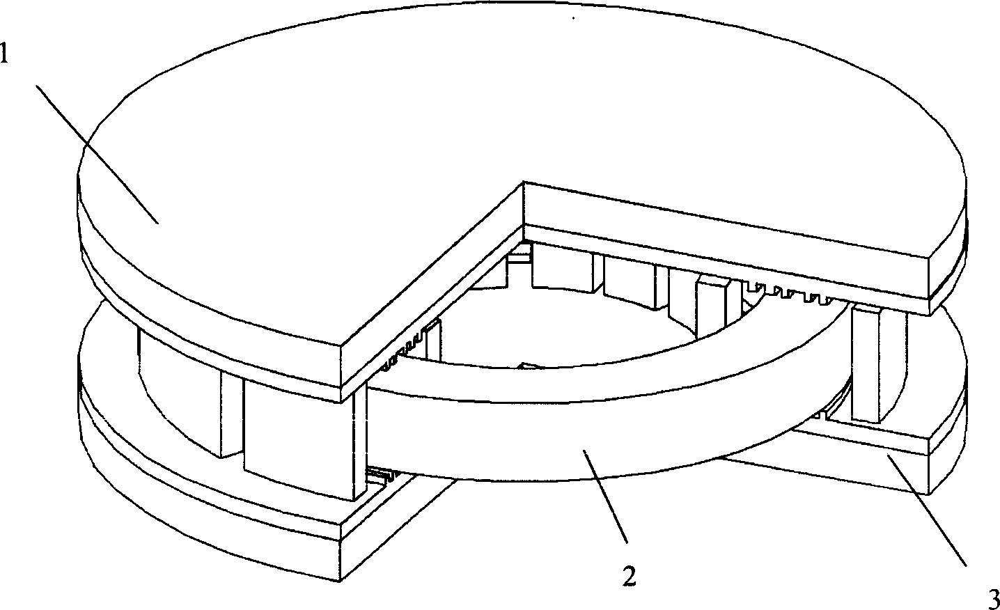
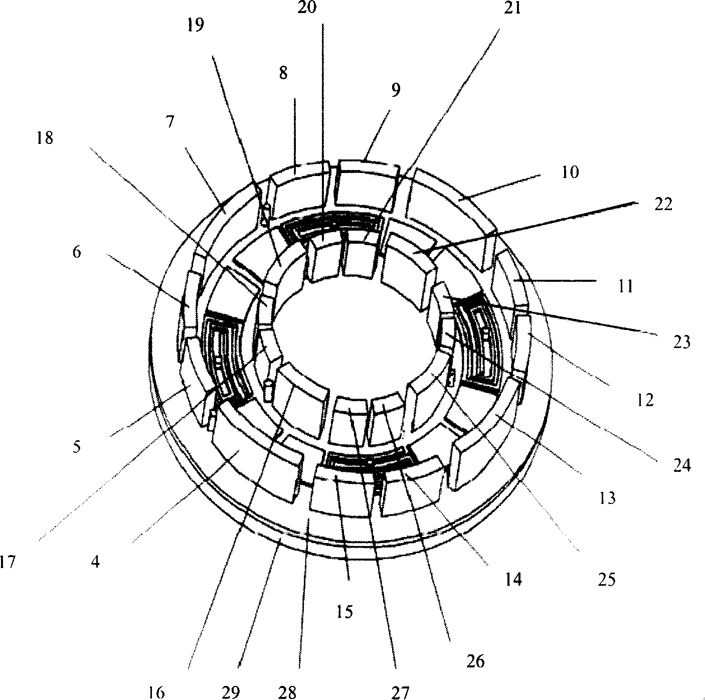
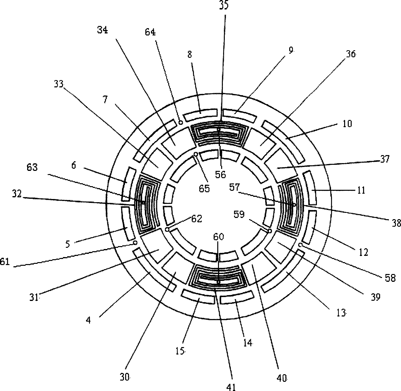
[0015] Such as figure 1 , figure 2 , image 3 , Figure 4 , Figure 5 As shown, the present invention includes: an upper stator 1, a rotor 2, and a lower stator 3, wherein the lower stator 3 includes: the lower left public detection electrode 4 on the outer side of the lower stator, the first left side detection electrode 5 on the left side of the lower stator, and the second left numbered electrode on the lower stator side. Outer detection plus moment electrode 6, lower stator outer upper left common detection electrode 7, lower stator upper No. No. 1 on the right of the outer side of the sub-right, the detection plus moment electrode 11, the second side of the lower stator right side, the detection plus moment electrode 12, the outer side of the lower stator, the lower right common detection electrode 13, the next side of the lower stator, the detection plus moment electrode 14, the second side of the lower stator Measuring and detecting moment-adding electrode 15, lowe...


PUM


Abstract

Disclosed is a static electricity supported suspending electromagnetic induction rotary micro gyroscope which comprises a upper stator, a rotor and a lower stator. Wherein the upper and lower stators are individually installed with an adding moment detecting electrode, a public electrode and a rotary driving coin, and the stators are connected together via side electrode and form a circle type cavity in which located a circle type rotor to form a gyroscope system. The invention employs the circle type rotor to perform detection and adding moment control via the side electrode which can add lateral rigidity of the system. A barrier cylinder is used to prevent the rotor contacting the upper and lower stators and to increase stability of the system.

Description

technical field [0001] The invention relates to a micro-gyroscope, in particular to an electrostatically supported suspension electromagnetic induction rotating micro-gyroscope, which belongs to the technical field of micro-electromechanical systems. technical background [0002] The suspended rotor micro-gyroscope designed and manufactured by MEMS technology has the potential advantages of small size, low cost and high precision, and has broad application value. Researchers from all over the world are carrying out research work in this area. [0003] In Chinese patent CN03141542.3, publication date 2004.02.25, the patent name "Magnetic Suspension Rotor Azimuth Micro-Gyroscope" reports a magnetic levitation rotor micro-gyroscope that utilizes eddy current suspension and rotation. The gyroscope is designed and manufactured using MEMS technology. The patent document It is said that the gyroscope has the characteristics of low cost and high precision, but due to the use of eddy...

Claims


Application Information

Patent Timeline
IPC IPC(8): G01C19/24H02N15/00H02K17/16
Inventor 张卫平周海军陈文元
Owner SHANGHAI JIAO TONG UNIV
Why Eureka
Try Eureka