Gear shifting motor

A technology for shifting motors and components, which is applied to electromechanical devices, electrical components, and electric components, etc., can solve the problems of large impact force, incompatibility, and inability to accurately calculate the motor shaft speed, and achieve the effect of accurate shifting and safety protection.

Inactive Publication Date: 2006-12-13
浙江瑞鹏汽车电器有限公司
View PDF0 Cites 2 Cited by
  • Summary
  • Abstract
  • Description
  • Claims
  • Application Information

AI Technical Summary

Problems solved by technology

Its disadvantages are: it directly outputs the torque through the gear shaft, which generates a large impact force, which is easy to damage the driven parts; the speed of the motor shaft cannot be accurately calculated
Especially when the shift fork that drives the car that is converted from manual gear to automatic gear shifting works, it is even more inappropriate.

Method used


Image

  • Gear shifting motor
  • Gear shifting motor
  • Gear shifting motor

Examples


Embodiment Construction

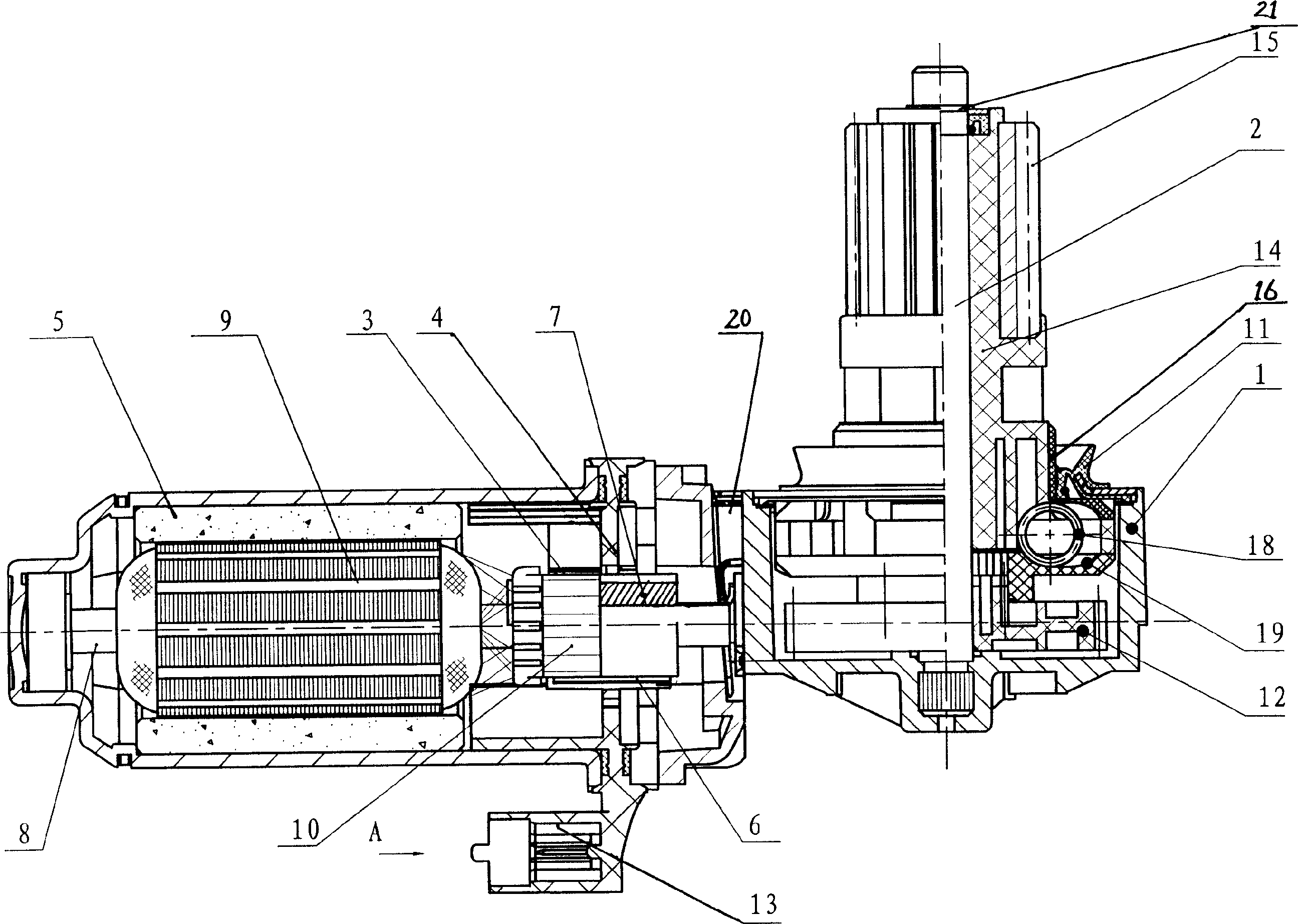
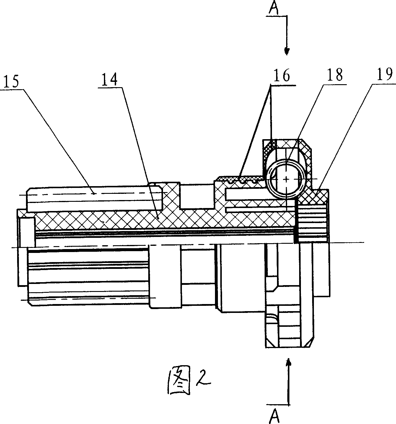
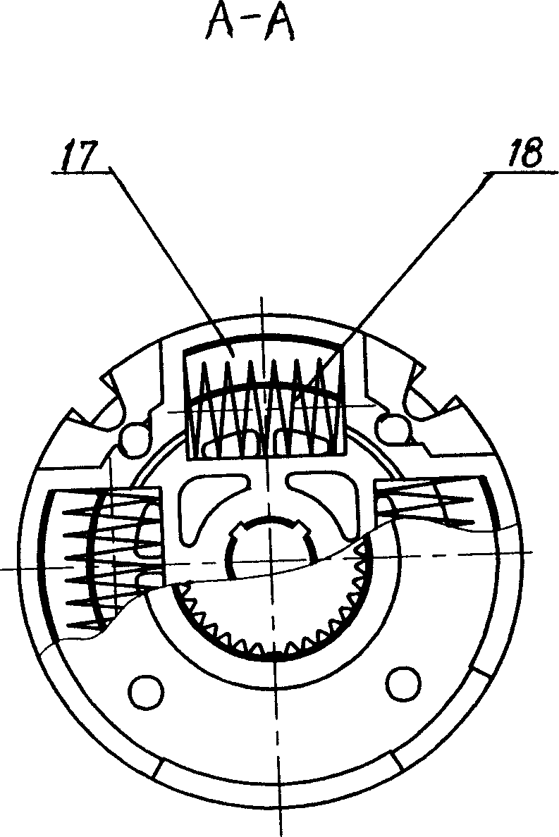
[0012] refer to Figure 1 to Figure 4 It can be seen that the shift motor of the present invention includes a reducer housing assembly, a brush holder assembly, a rotor assembly, a stator assembly 5, a driving gear 12, a gear cover assembly 11, a plug connector 13, and a blocking cover assembly 20, wherein the reducer housing The assembly includes a reducer housing 1 and a gear shaft 2. The brush holder assembly includes a brush 3 and a brush holder 4. The rotor assembly includes a motor shaft 8, a rotor winding 9, and a commutator 10. The brush holder assembly includes Magnetic Hall inductor 6 (permanent magnet is housed on its circuit board) is housed on frame 4, and the wiring of this Hall inductor 6 is located in plug connector 13, on the motor shaft 8 of described rotor assembly, Corresponding to the position of the magnetic Hall sensor, there is an induction counting gear 7 (the uniformity of the magnetic pole angle is high, and the material is pure electric iron); the r...


PUM


Abstract

The invention discloses a shift motor, which is characterized by the following: loading Hall inducer 6 with magnetic property on the brush rocker 4 of brush rocker component; casing induction counting gear 7 corresponding to Hall inducer on the motor shaft 8 of rotor component; connecting reducer case 1 of reducer case component and gear shaft 2; casing buffer bulk 14 on the gear shaft 2; casing buffer gear 15, plastic sleeve 16 on the outer and inner sides of buffer bulk 14 separately; opening spring groove 17 with buffer spring 18 on the top of buffer bulk 14; connecting lid gear 19 in the inner part of buffer bulk 14; gearing lid gear 19 and positive gear 12. The invention protects driven part effectively, which is fit for automobile fork and shift sequently and precisely.

Description

1. Technical field [0001] The invention relates to an electric machine. 2. Background technology [0002] Existing ordinary motors are generally composed of a reducer housing assembly, a brush holder assembly, a rotor assembly, a stator assembly, a driving gear, a gear cover assembly, etc., wherein the reducer housing assembly includes a reducer housing, a gear shaft, and the gear shaft and The housing of the reducer is movably connected, the driving gear is installed on the gear shaft, and the gear shaft is connected with the driven parts outside the motor; the rotor assembly includes the motor shaft, rotor winding, and commutator. Its working process is: the driving gear is driven by the rotation of the motor shaft to make the gear shaft rotate, thereby driving the driven parts to work. Its disadvantages are: it directly outputs torque through the gear shaft, which generates a large impact force and easily damages the driven parts; the speed of the motor shaft cannot be a...

Claims


Application Information

Patent Timeline
Patent Type & Authority Applications(China)
IPC IPC(8): H02K7/116H02K11/00G01P3/44G01P3/487H02K11/215
Inventor 林建光方树功丛子元王华东蔡华银
Owner 浙江瑞鹏汽车电器有限公司
Why Eureka
Try Eureka