
Electronic park brake valve system for air brakes vehicles

A parking brake cylinder, vehicle braking technology, applied in the direction of brake transmission, brakes, brake components, etc., can solve the problems of difficult installation, increased parking brake release time, occupying space, etc.

Inactive Publication Date: 2006-12-20
HALDEX BRAKE
View PDF3 Cites 14 Cited by
  • Summary
  • Abstract
  • Description
  • Claims
  • Application Information

AI Technical Summary

Problems solved by technology

The large amount of piping is not only expensive, heavy and relatively difficult to install (and thus requires a lot of installation time), but also the long piping between different components creates a delay in achieving the required system pressure, such as parking brake release time increased
Furthermore, the valves and system components themselves are expensive, take up a lot of space, and add significantly to the weight of the vehicle

Method used


Image

  • Electronic park brake valve system for air brakes vehicles
  • Electronic park brake valve system for air brakes vehicles
  • Electronic park brake valve system for air brakes vehicles

Examples


Embodiment Construction

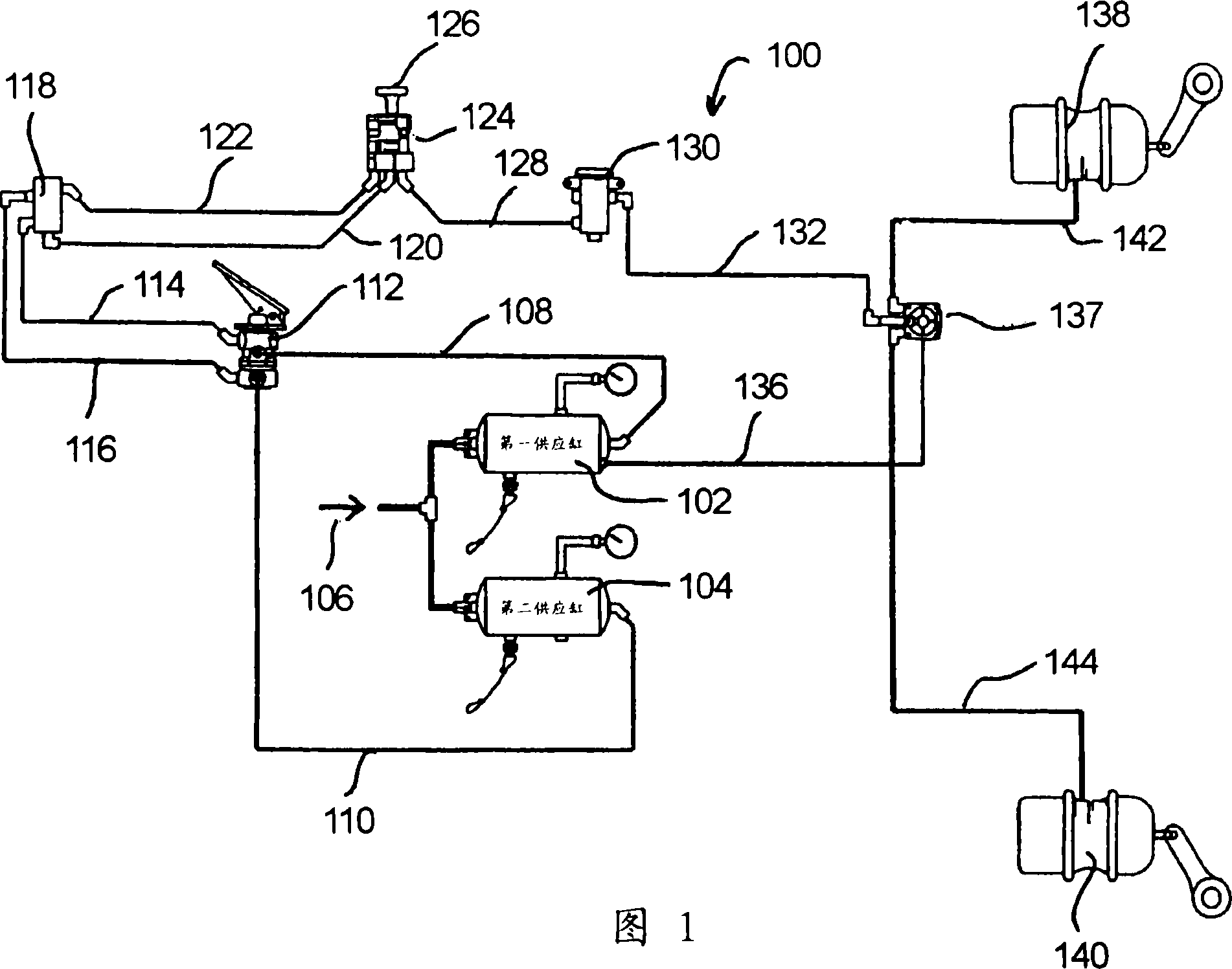
[0024]As shown in FIG. 1 , a typical heavy vehicle pneumatic braking system 100 in the prior art is shown. The system 100 includes a primary compressed air supply cylinder 102, a secondary compressed air supply cylinder 104, both of which receive compressed air from a compressed air source (shown by arrow 106), typically a compressor. The primary compressed air supply cylinder 102 and the secondary compressed air supply cylinder 104 are connected by conduits 108, 110 to a brake pedal 112, which is located within the cab, generally within easy reach of the driver's feet.

[0025] The brake pedal 112 is connected by conduits 114, 116 to a manifold 118 which is connected by conduits 120, 122 to a push / pull dual check valve (PPDC) 124 which typically includes a push / pull handle 126 located in the cab, This handle is normally located on the bulkhead within the driver's reach. PPDC valve 124 is connected by conduit 128 to switch valve 130 which is connected by conduit 132 to relay ...


PUM


Abstract

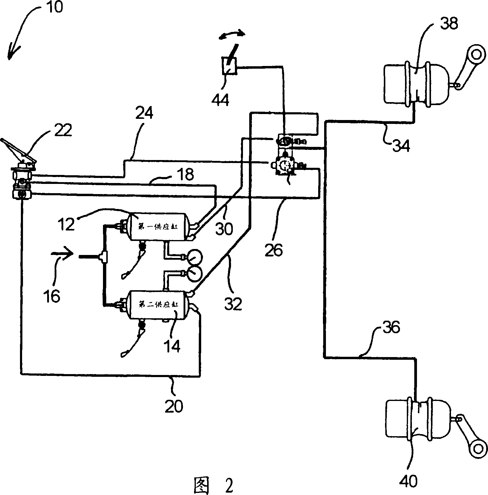
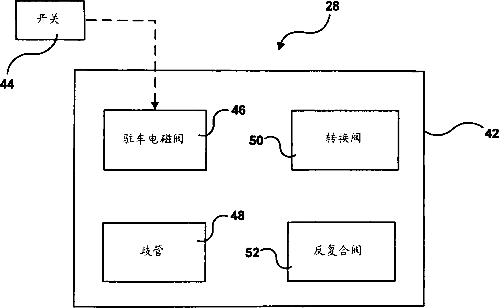
A vehicle brake system includes a source of fluid pressure adapted to supply a braking force a brake actuator including a parking brake chamber, and a combination valve fluidly coupling the brake actuator to the source of pressure, the combination valve having an inlet fluidly coupled to the source of pressure and an outlet fluidly coupled to the brake actuator. The combination valve includes within a single housing (i) a solenoid responsive to electrical signals to move from one position in which the parking brake chamber is fluidly coupled to the source of pressure in order to pressurize the parking brake chamber and release the parking brake, and another position in which the parking brake chamber of the brake actuator is vented in order to exhaust pressure within the parking brake chamber so that the parking brake is applied, and (ii) at least one of a manifold, an inversion valve, a double check valve and an anti-compounding valve.

Description

technical field [0001] This application relates to a pneumatic braking system, such as that used in heavy vehicles, and more particularly to control valves for said system, especially those used in parking brake systems . Background technique [0002] Most of today's heavy vehicle braking systems use compressed air to apply the brakes. In such systems, a control signal is typically transmitted by the driver of the vehicle to a control valve of the braking system in order to apply the brakes. Such braking generally falls into two categories: service braking and parking braking. Service braking typically slows a moving vehicle to a stop. The parking brake is mainly used to help prevent the vehicle from moving from a fixed parking place, and may also be used to slow down the moving vehicle in emergency situations when the service brake fails, thereby providing a redundant braking circuit. [0003] For service braking, the driver typically depresses the brake pedal, which ac...

Claims


Application Information

Patent Timeline
Patent Type & Authority Applications(China)
IPC IPC(8): B60T13/68B60T15/52
CPCB60T17/04B60T13/38B60T15/04B60T13/26B60T13/00
Inventor 乔·胡佛罗伯特·鲁道夫戴维·G·恩格尔伯特诺布尔·汉密尔顿
Owner HALDEX BRAKE
Learn More