Unlock instant, AI-driven research and patent intelligence for your innovation.

Backlight unit manufacturing method, backlight unit, electro-optical device, and electronic device

The technology of a backlight assembly and a manufacturing method is applied in the manufacture of backlight assemblies, backlight assemblies, optoelectronic devices, and electronic equipment, and can solve problems such as difficult large-scale, reduced screen brightness, and uneven brightness, so as to reduce light leakage and reduce brightness The effect of reducing unevenness and brightness unevenness

Inactive Publication Date: 2006-12-20
SEIKO EPSON CORP
View PDF2 Cites 2 Cited by
  • Summary
  • Abstract
  • Description
  • Claims
  • Application Information

AI Technical Summary

Problems solved by technology

[0006] However, in this method, since the number of linear lights that can be mounted is limited, when a large screen is formed, the brightness of the screen cannot be ensured.
In addition, due to the weight of the light guide, it is also difficult to increase the size
In the direct type in which linear lights are arranged directly below the screen, since the number of linear lights is increased according to the size of the screen, although there is no problem in brightness, the brightness of the linear lights themselves is poor, and the linear Uneven brightness caused by the difference in brightness between the part directly under the lamp and the part without it will become a problem again.
In addition, if the linear lights are placed away from the display surface, the brightness unevenness will be improved, but the brightness of the screen will decrease and become dull.
Moreover, it will be difficult to achieve thinning of the backlight assembly
In order to brighten the screen, the number of linear lights should be increased corresponding to the size of the screen. However, due to the increase in the number, heat generation and cost will become problems.

Method used


Image

  • Backlight unit manufacturing method, backlight unit, electro-optical device, and electronic device
  • Backlight unit manufacturing method, backlight unit, electro-optical device, and electronic device
  • Backlight unit manufacturing method, backlight unit, electro-optical device, and electronic device

Examples


Embodiment approach

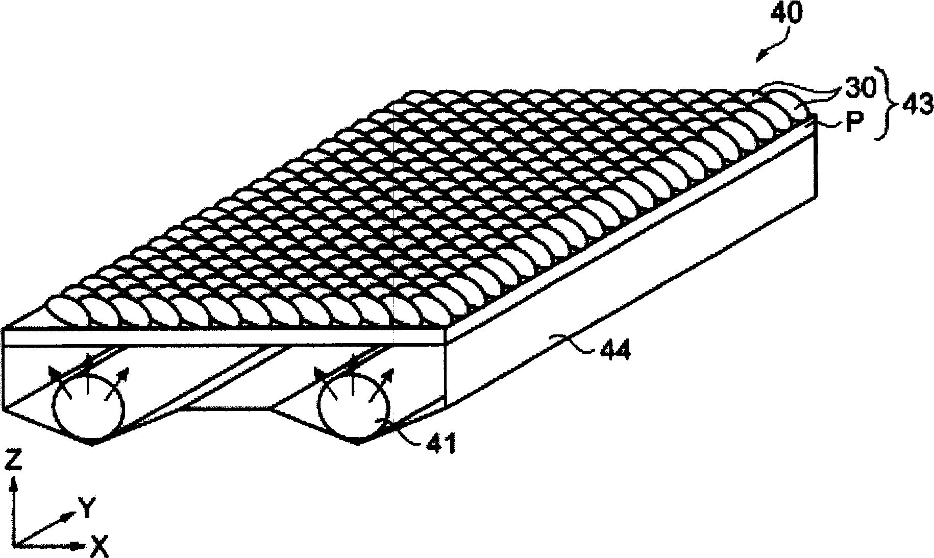
[0042]In this embodiment, a backlight unit having a diffuser plate provided with elliptical microlenses formed on a substrate by a droplet discharge method will be described. In addition, the long-axis direction of the linear lamp and the long-axis direction of the elliptical microlens are arranged so as to cross diagonally.

[0043] figure 1 It is a schematic perspective view showing an example of the backlight unit 40 of this embodiment. refer to figure 1 , the backlight assembly 40 of the present invention will be described.

[0044] Such as figure 1 As shown, the backlight assembly 40 is a direct type. The backlight unit 40 is composed of a linear light 41 as a light source, a diffusion plate 43 for diffusing light irradiated from the linear light 41 , and a reflector 44 for reflecting the light. The diffusion plate 43 has a plurality of elliptical microlenses 30 formed on the substrate P. As shown in FIG. There are a plurality of linear lights 41 (two in this exampl...


PUM

PropertyMeasurementUnit
viscosityaaaaaaaaaa
particle diameteraaaaaaaaaa

Abstract

A backlight unit that includes a light source emitting a light; and a diffuser plate that diffuses the light coming from the light source. In the backlight unit, the diffuser plate is provided with a plurality of ellipsoid-shaped microlenses, and disposed to make the microlenses and the light source intersect each other in each major axis direction.

Description

technical field [0001] The invention relates to a manufacturing method of a backlight assembly, a backlight assembly, an optoelectronic device, and electronic equipment. Background technique [0002] Conventionally, in a liquid crystal display device which is an optoelectronic device, there is a method in which an optical sheet having a plurality of microlenses is arranged in a backlight assembly for a liquid crystal display incorporated in the liquid crystal display device, and the light source for illumination from the backlight assembly The light is efficiently concentrated to the liquid crystal element (pixel). In addition, many methods of forming microlenses using a droplet discharge method have also been reported (for example, Patent Document 1, etc.). [0003] For example, as disclosed in Patent Document 2, it is an edge-light type (side-light type) backlight unit having a structure in which a linear lamp as a light source is arranged along a side surface of a light ...

Claims


Application Information

Patent Timeline
Patent Type & Authority Applications(China)
IPC IPC(8): G02F1/1335G02B3/00G02F1/1333G02B5/02
CPCG02F1/133606G02F1/133604G02F1/1335
Inventor 长谷井宏宣斋藤重夫稻垣显
Owner SEIKO EPSON CORP