Fluidized bed reactor system having an exhaust gas plenum

A technology of reactor system and ventilation system, applied in fluidized bed boilers, fluidized bed combustion equipment, chemical instruments and methods, etc., can solve problems such as complex structures

Inactive Publication Date: 2006-12-20
KAUTEX TEXTRON GMBH & CO KG
View PDF0 Cites 7 Cited by
  • Summary
  • Abstract
  • Description
  • Claims
  • Application Information

AI Technical Summary

Problems solved by technology

Such a structure is complex and can cause stress due to differential thermal expansion

Method used


Image

  • Fluidized bed reactor system having an exhaust gas plenum
  • Fluidized bed reactor system having an exhaust gas plenum
  • Fluidized bed reactor system having an exhaust gas plenum

Examples


Embodiment Construction

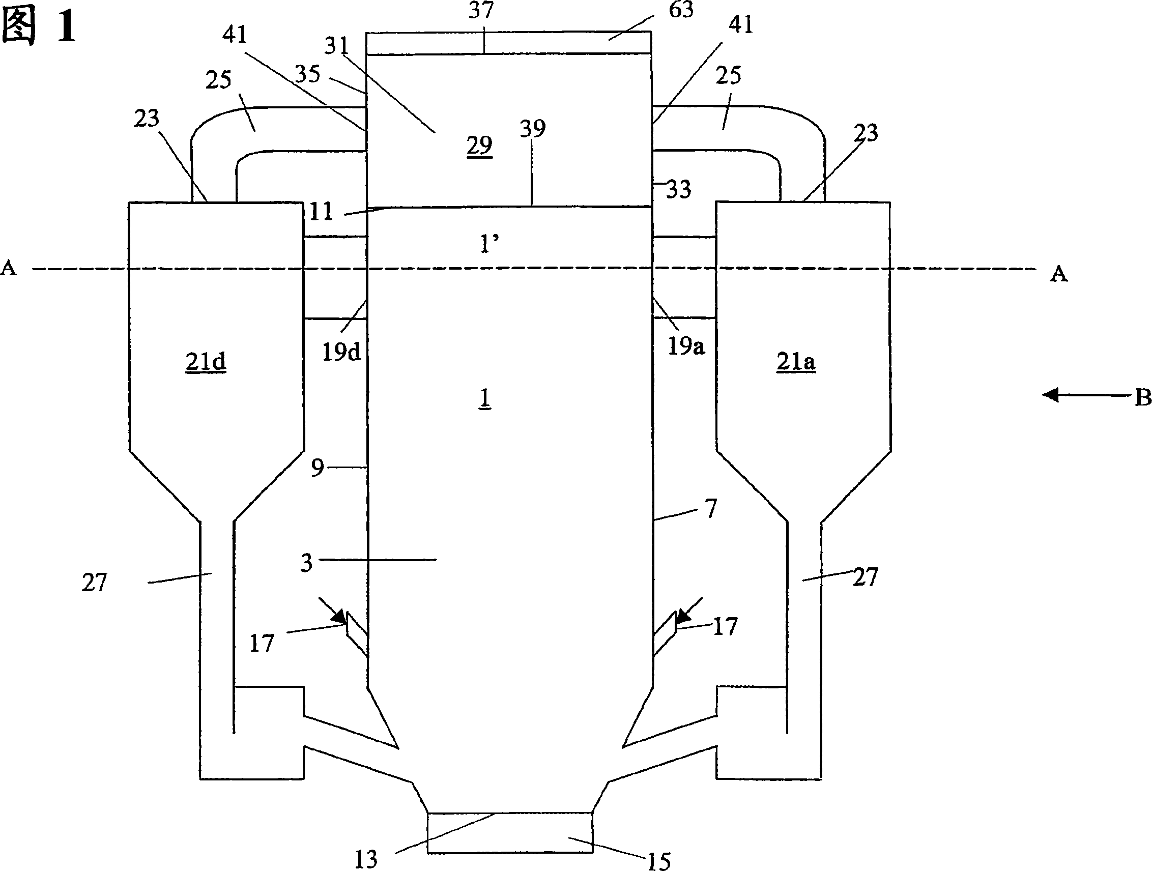
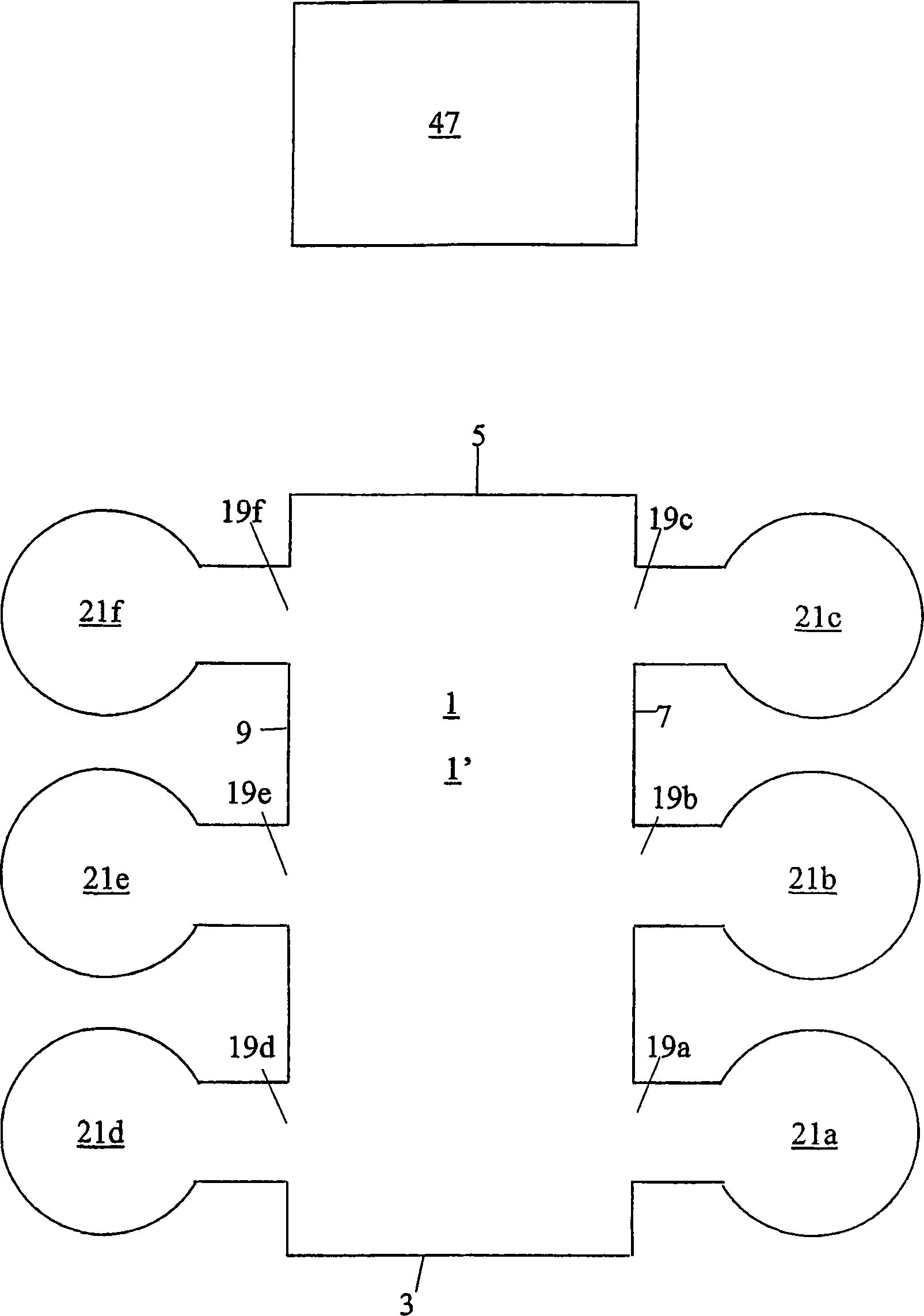
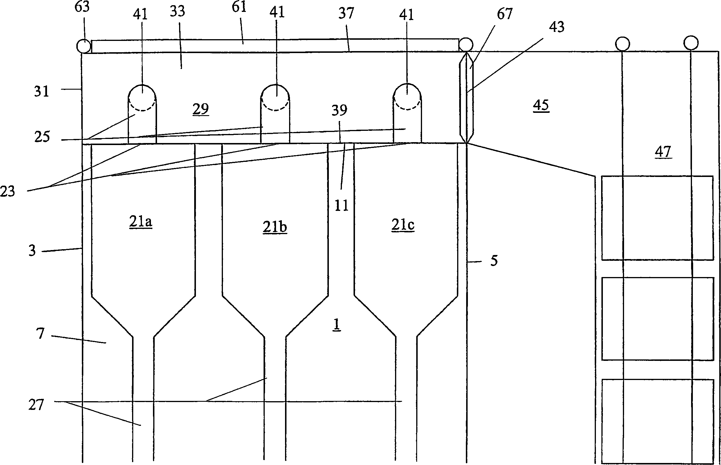
[0038] As shown in Figures 1, 2 and 3, the circulating fluidized bed reactor system includes a reaction chamber 1 in which a fluidized bed of solid particles is arranged. The reaction chamber 1 includes a front wall 3, a rear wall 5, a right side wall 7 and a left side wall 9, a top 11, and a bottom 13, and the chamber is formed by a common water tube plate, which includes water tubes connected by fins. The reaction chamber 1 includes a mechanism 15 for introducing fluidization gas, such as a nozzle or a ventilation pipe; a mechanism 17 for introducing fuel, such as a pneumatic or gravity fuel conveyor. The side walls 7, 9 of the reaction chamber are provided with six discharge ports 19a to 19f, which can discharge the particle suspension of the exhaust gas and the solid particles formed in the reaction chamber 1 through the upper part 1' of the reaction chamber 1. The outlets 19a to 19f of the reaction chamber are respectively provided with six particle separators 21a to 21f ...


PUM


Abstract

An arrangement for directing exhaust gases from at least one particle separator (21a,d) of a circulating fluidized bed reactor system to a heat recovery section includes a gas plenum (29) located above and integrated with a reaction chamber (1). The walls of the gas plenum are provided with at least one inlet opening (41) for cleaned exhaust gases, each of which is coupled with a discharge duct (25) connected to one of the particle separators, for directing the cleaned exhaust gases from the particle separators to the gas plenum, from where the cleaned exhaust gases are directed to the heat recovery section. The reaction chamber is at least partially formed by water tube panels, and the enclosure of the gas plenum is formed by water tube panels as extensions of water tube panels of the reaction chamber.

Description

technical field [0001] The present invention relates to an arrangement of a circulating fluidized bed reactor system for directing waste gas from at least one particle separator to a heat recovery section. Background technique [0002] The circulating fluidized bed reactor system includes a reaction chamber in which a fluidized bed of solid particles is arranged, and the particle suspension and solid particles of the waste gas can be discharged through at least one discharge port arranged on the upper part. Each discharge port is connected to a particle separator, which separates solid particles and particle suspensions. The upper part of each particle separator is provided with a gas discharge port, which is used to discharge the clean exhaust gas flow. Clean exhaust gas is directed from the particle separator to the heat recovery section of the circulating fluidized bed reactor system. The lower part of each particle separator is connected to the return line, and then co...

Claims


Application Information

Patent Timeline
Patent Type & Authority Applications(China)
IPC IPC(8): F23C10/10F22B31/00F23M5/08
CPCF23M5/08F22B31/0084F22B31/003F23C10/10B01J8/18F23C10/00F23M5/00F22B31/00
Inventor S·达林
Owner KAUTEX TEXTRON GMBH & CO KG
Why Eureka
Try Eureka