Solar-thermal fluid-wall reaction processing
a technology of solar energy and reaction technology, applied in the field of solar energy reactors, can solve the problems of preventing continuous operation, affecting the efficiency of production, and the current method of hydrogen production, and achieve the effects of reducing or preventing the produced carbon black, short residence time, and cost-effectiveness
- Summary
- Abstract
- Description
- Claims
- Application Information
AI Technical Summary
Benefits of technology
Problems solved by technology
Method used
Image
Examples
example 1
Operation of a Three-Shell Reactor
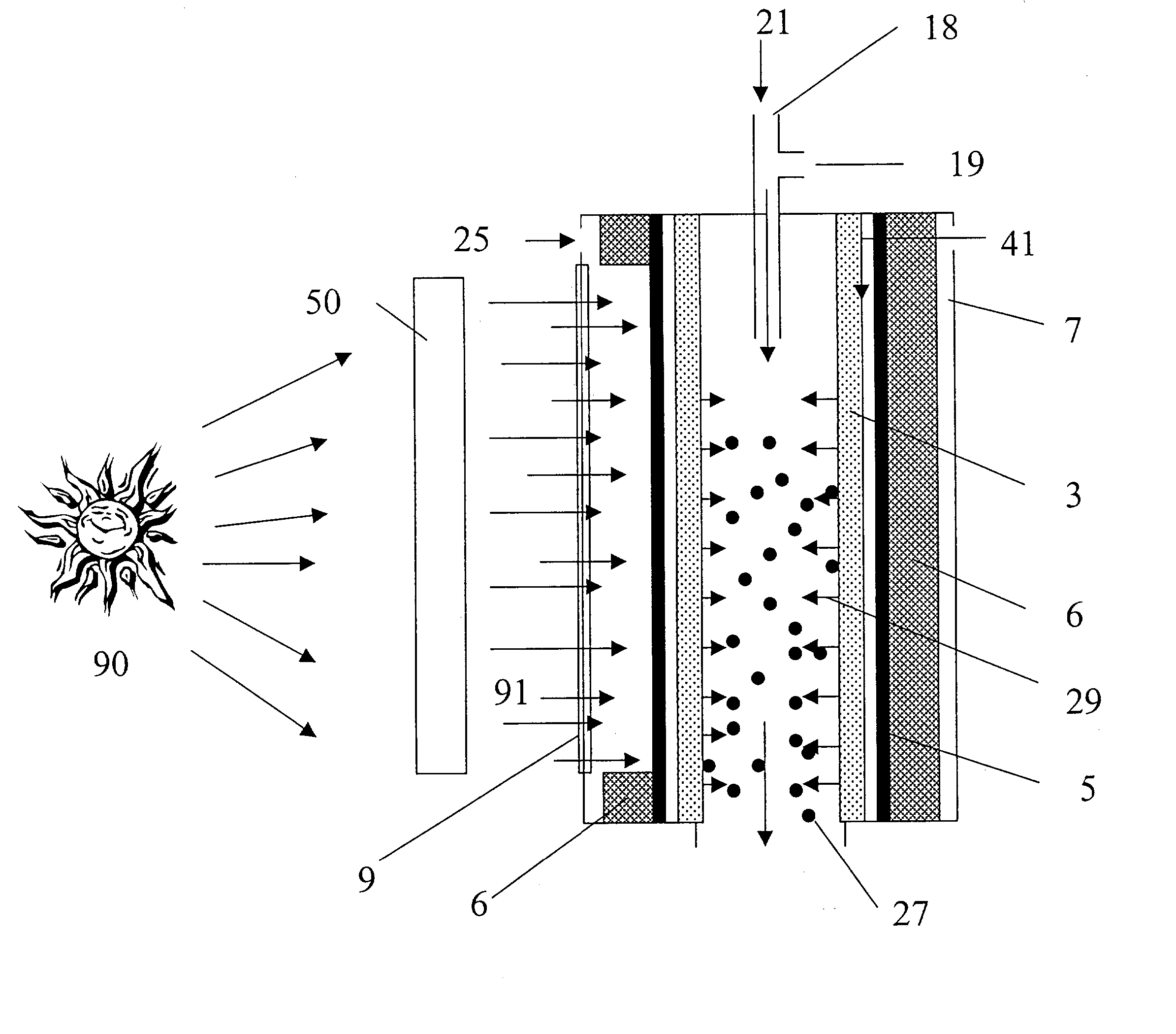
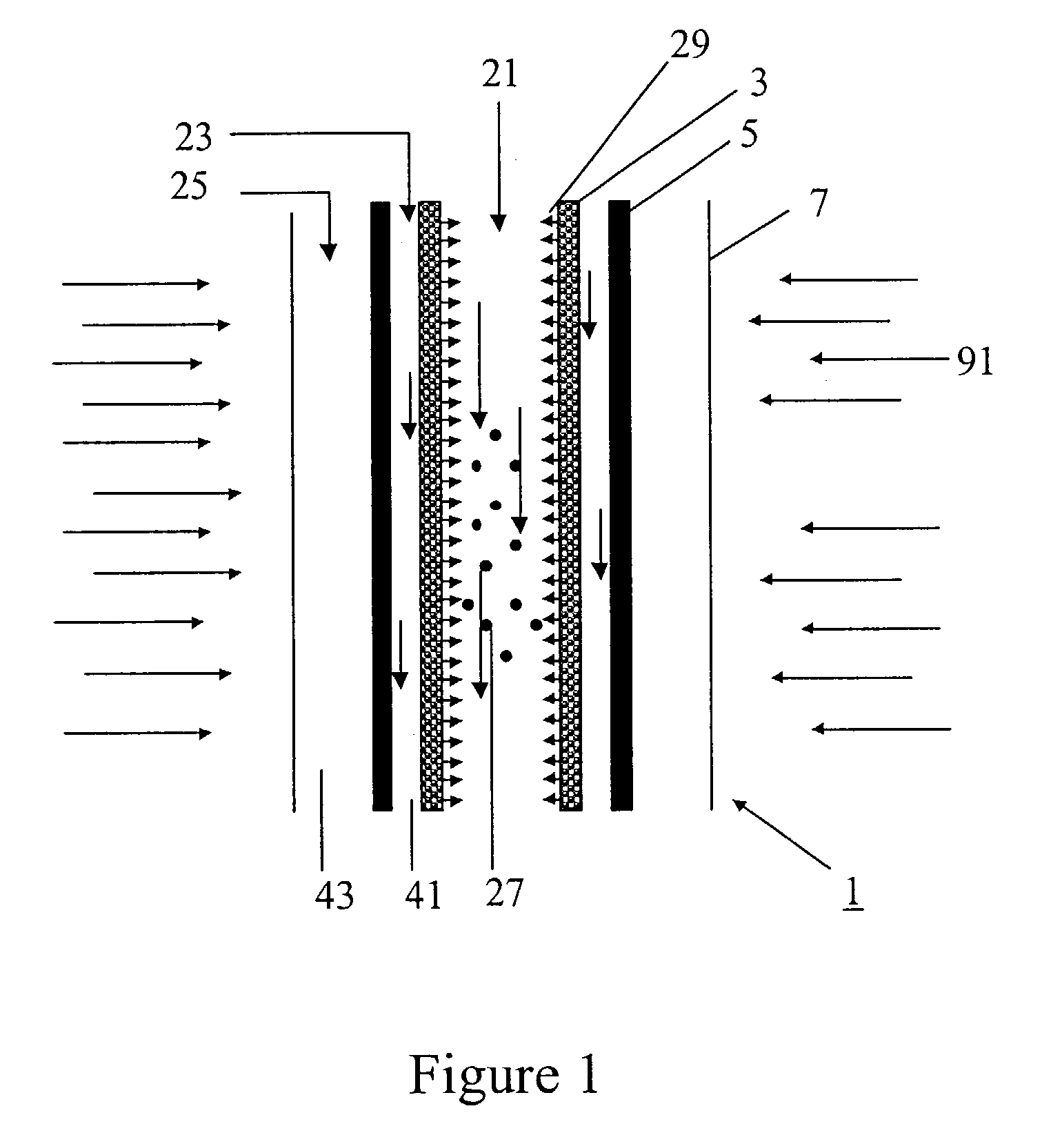
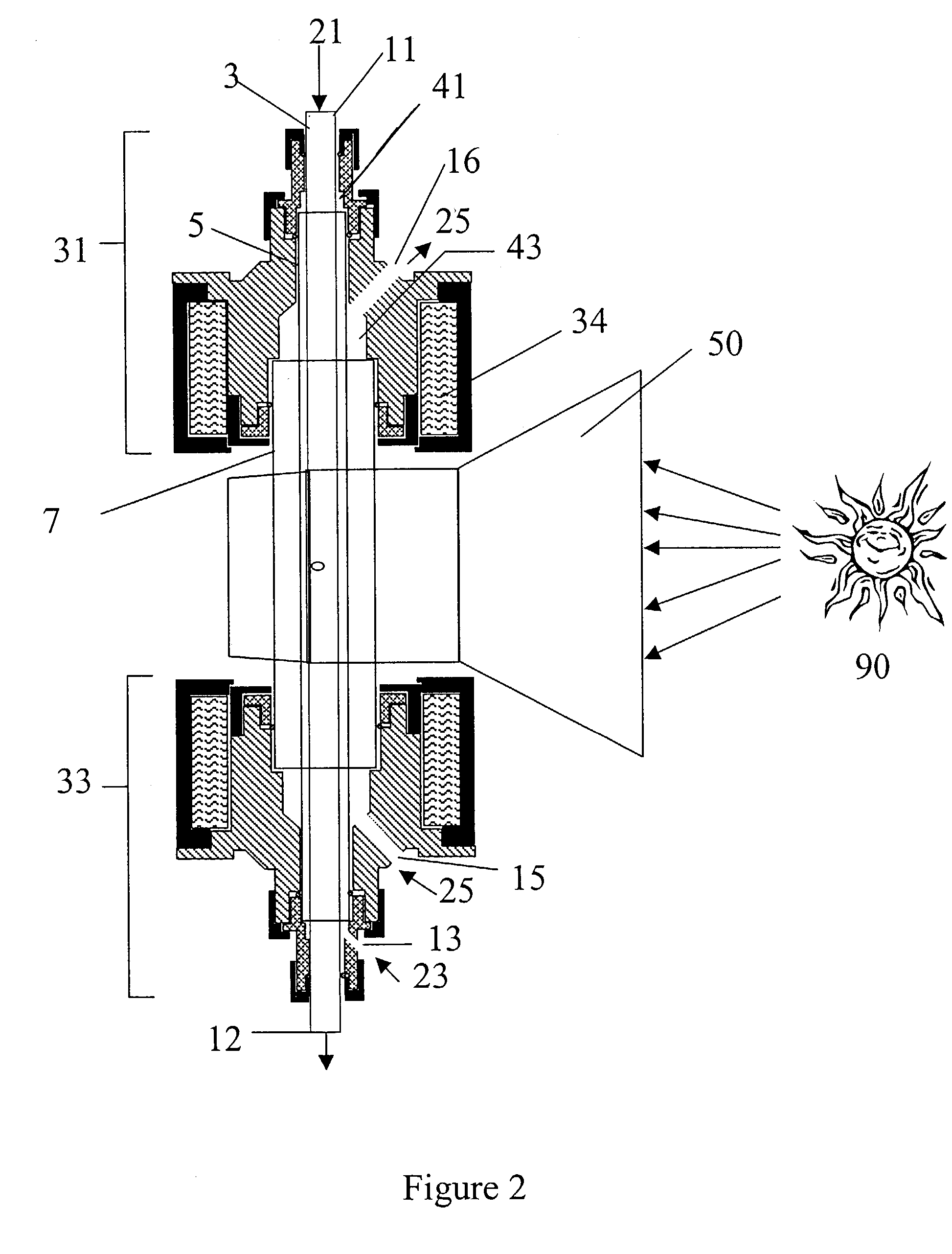
[0087]In accordance with the present invention, a concentric three-tube aerosol transport reactor was constructed and vertically interfaced to the HFSF at NREL. The aerosol transport reactor consisted of an outer 5.1 cm outside diameter×4 mm thick×24 cm long quartz “protection” tube, a central 2.4 cm outside diameter×4 mm thick×35.6 cm long graphite “heating” tube, and a 1.8 cm outside diameter×6 mm thick×44 cm long graphite “reaction” tube. The “reaction” tube consisted of a 30 cm long porous graphite section with 7 cm of solid graphite tube on both ends of the “reaction” tube. The porosity of the graphite tube was 49% with a permeability of air (at standard temperature and pressure (STP)) of 1 ft3 / ft2 / min. It was a sunny day. A secondary concentrator delivered 7.4 kW of solar-thermal power over a 9.4 cm length. The concentrator was positioned concentrically around the outer quartz “protection” tube. A 99% methane / 1% argon gas was fed at a rate of ...
example 2
Operation of a Three-Shell Reactor with No “Fluid-Wall” Gas Flow
[0088]The process conditions of Example 1 were repeated except that no “fluid-wall” hydrogen gas was flowed through the porous “reaction” tube. Within 8 minutes, the process was shut down due to difficulties maintaining feed gas flow using mass flow controllers. After cooling, the reactor was dismantled and inspected. It was found that carbon was deposited inside of the “reaction” tube. The carbon was analyzed by x-ray diffraction and found to contain a large graphitic content. This comparative example illustrates that, without the fluid-wall, the reactor plugs and prevents continuous operation.
example 3
Reactor Operation with Increased Fluid-Wall and Purge Gas Flow Rates
[0089]The apparatus described in Example 1 was used except that the “fluid-wall” gas was changed to argon. It was fed at a rate of 4 slpm through the porous tube wall. In addition, the argon “purge” gas flow was increased to 10 slpm.
PUM
 Abstract
Description
Claims
Application Information
 - R&D
- Intellectual Property
- Life Sciences
- Materials
- Tech Scout
- Unparalleled Data Quality
- Higher Quality Content
- 60% Fewer Hallucinations
Browse by: Latest US Patents, China's latest patents, Technical Efficacy Thesaurus, Application Domain, Technology Topic, Popular Technical Reports.
© 2025 PatSnap. All rights reserved.Legal|Privacy policy|Modern Slavery Act Transparency Statement|Sitemap|About US| Contact US: help@patsnap.com


