
Reactor system with multi-directional reaction chamber

a reactor system and reaction chamber technology, applied in the field of reactor systems, can solve the problems of reducing the efficiency of the reactor system to produce finished products, the transfer tool may not be able to keep up with the required substrate transfer in the required time, and the delay of substrate transfer between reaction chambers

Pending Publication Date: 2021-08-12
ASM IP HLDG BV
View PDF4 Cites 128 Cited by
  • Summary
  • Abstract
  • Description
  • Claims
  • Application Information

AI Technical Summary

Benefits of technology

The patent describes a reactor system that includes multiple reaction chambers, transfer chambers, and gate valves. These components work together to allow for the transfer of substrates between the chambers and the transfer tools. The system can also include additional reaction chambers, transfer tools, and gate valves. The technical effect of this system is to provide a more efficient and flexible way of transferring substrates between different reaction chambers for processing.

Problems solved by technology

However, if a transfer tool is required to complete two or three (or more) substrate transfers between reaction chambers in a limited amount of time as required by a substrate processing method, the transfer tool may not be able to keep up with the required substrate transfers in the required time.
In other words, with too many required substrate transfers between reaction chambers in a reactor system during a processing method, there may be a substrate “traffic jam,” causing delays in substrate transfers between reaction chambers relative to the desired timing of such substrate transfers and subsequent processing step(s).
Such waiting may decrease the efficiency of a reactor system to produce finished products (e.g., semiconductors) and / or may diminish the quality of the finished products.

Method used


Image

  • Reactor system with multi-directional reaction chamber
  • Reactor system with multi-directional reaction chamber
  • Reactor system with multi-directional reaction chamber

Examples


Embodiment Construction

[0025]Although certain embodiments and examples are disclosed below, it will be understood by those in the art that the disclosure extends beyond the specifically disclosed embodiments and / or uses of the disclosure and obvious modifications and equivalents thereof. Thus, it is intended that the scope of the disclosure should not be limited by the particular embodiments described herein.

[0026]The illustrations presented herein are not meant to be actual views of any particular material, apparatus, structure, or device, but are merely representations that are used to describe embodiments of the disclosure.

[0027]As used herein, the term “substrate” may refer to any underlying material or materials that may be used, or upon which, a device, a circuit, or a film may be formed.

[0028]As used herein, the term “atomic layer deposition” (ALD) may refer to a vapor deposition process in which deposition cycles, preferably a plurality of consecutive deposition cycles, are conducted in a process ...


PUM

PropertyMeasurementUnit
angleaaaaaaaaaa
angleaaaaaaaaaa
angleaaaaaaaaaa

Abstract

A reactor system may comprise a plurality of reaction chambers; a plurality of transfer chambers; and / or at least two gate valves coupled to each reaction chamber of the plurality of reaction chambers. A first gate valve of the at least two gate valves may fluidly couple a first respective reaction chamber of the plurality of reaction chambers to a first transfer chamber of the plurality of transfer chambers, and a second gate valve of the at least two gate valves may fluidly couple the first respective reaction chamber to a second transfer chamber of the plurality of transfer chambers. In various embodiments, each of the plurality of transfer chambers may comprise a transfer tool, wherein each transfer tool may be configured to transfer a substrate into and / or out of multiple reaction chambers.

Description

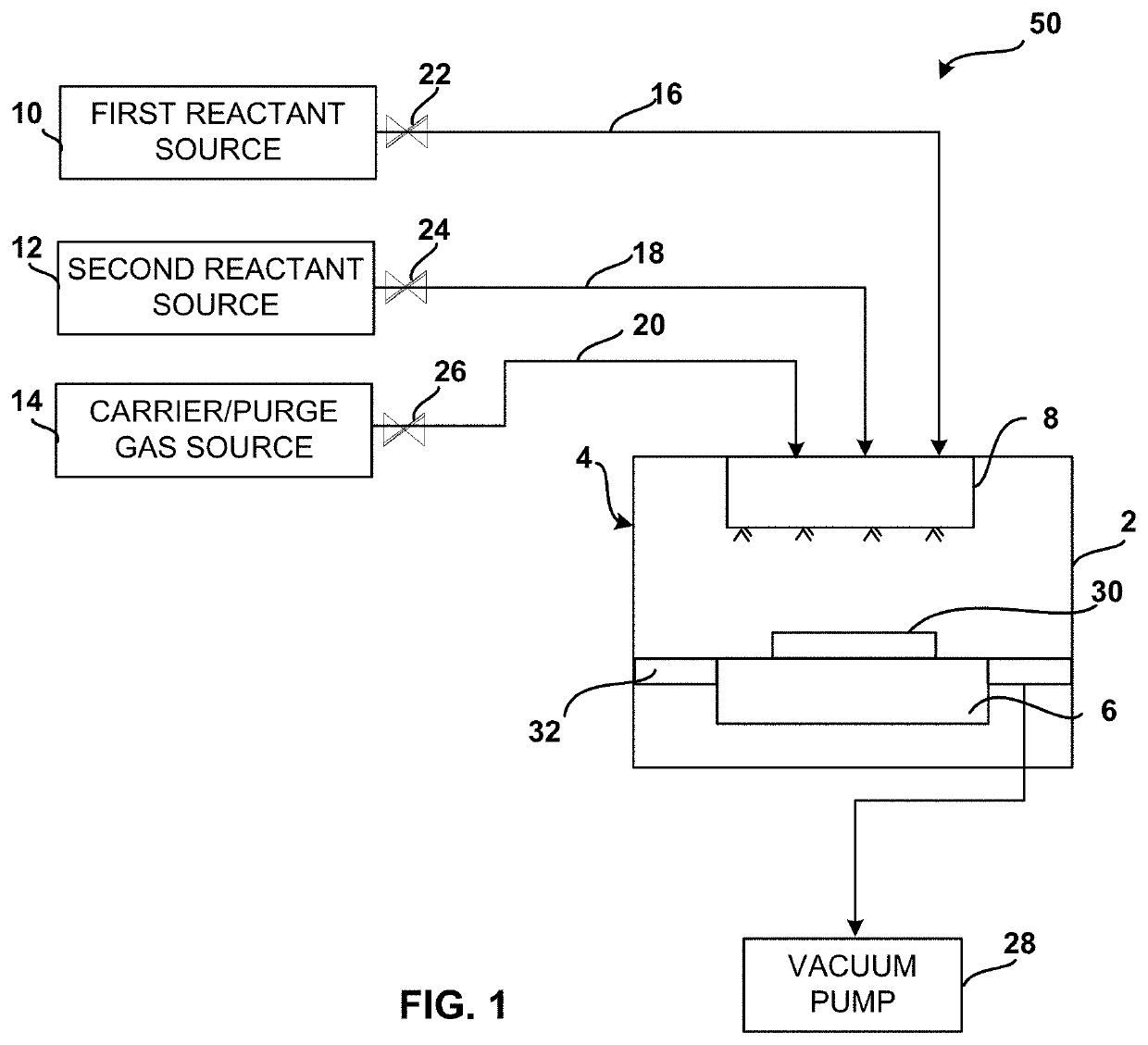
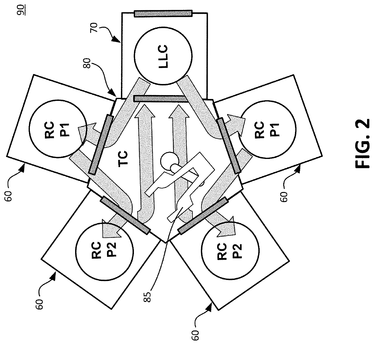
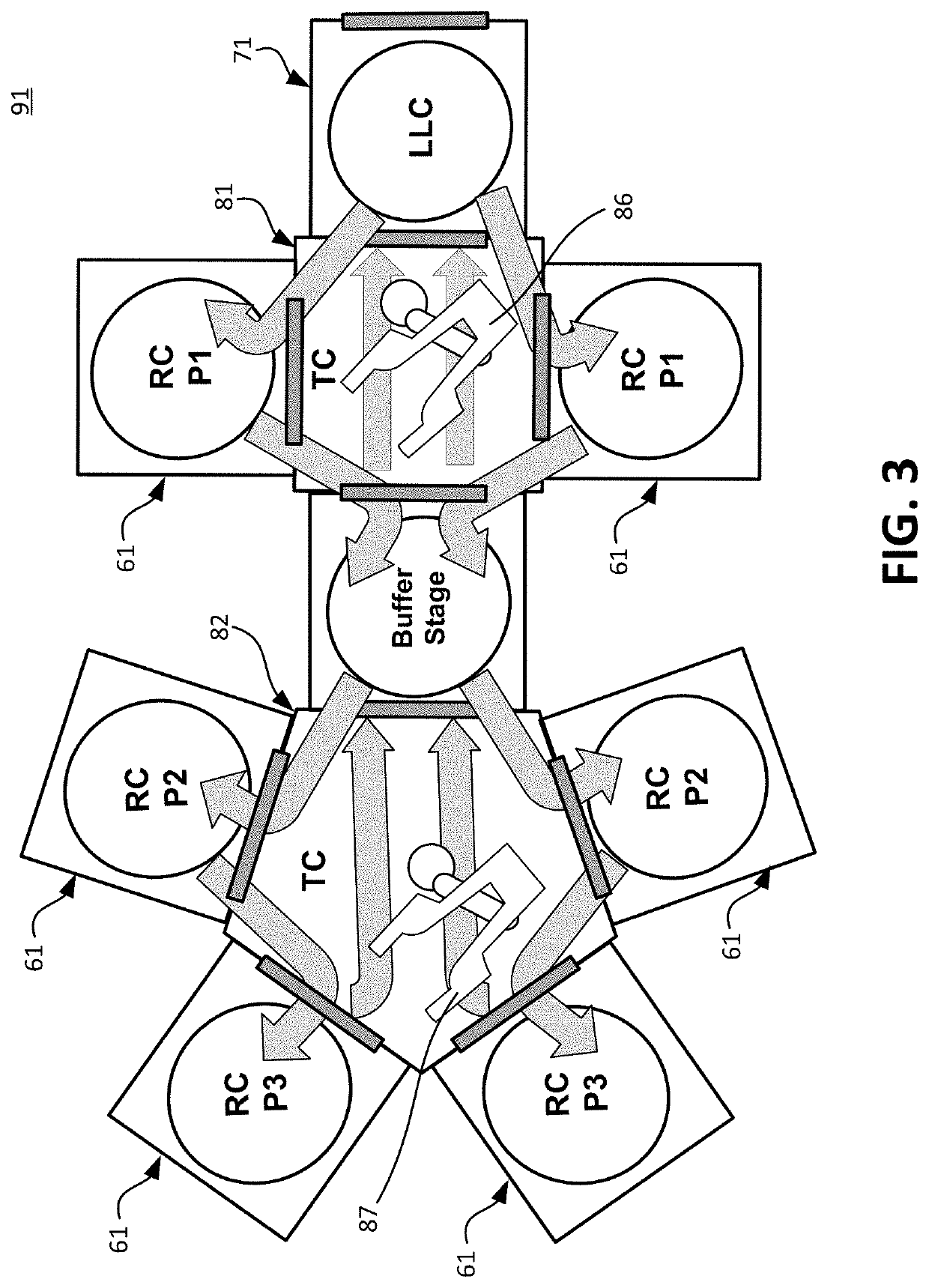
FIELD OF THE DISCLOSURE[0001]The present disclosure generally relates to a reactor system, particularly to a reactor system comprising one or more multi-directional reaction chambers.BACKGROUND[0002]Reactor systems may comprise various configurations of reaction chambers, substrate transfer chambers (TC), load lock chambers (LLC), and / or similar chambers or modules for processing substrates, for example. With reference to reaction chamber configuration 90, shown in FIG. 2, a number of reaction chambers 60 may be disposed around and / or coupled to a TC 80 comprising a transfer tool 85 for transferring substrates between reaction chambers 60. In another embodiment of a reactor system 91, shown in FIG. 3, a number of reaction chambers 61 may surround and / or be coupled to one or more TCs (e.g., TCs 81 and 82). Each TC may comprise one or more transfer tools (e.g., transfer tool 86 comprised in TC 81 and transfer tool 87 comprised in TC 82). Such embodiments of reactor systems may compris...

Claims


Application Information

Patent Timeline
Patent Type & Authority Applications(United States)
IPC IPC(8): C23C16/54C23C16/44C23C16/455
CPCC23C16/54C23C16/45544C23C16/4408H01L21/67745H01L21/67184H01L21/67161H01L21/67017H01L21/67126H01L21/67742C23C14/568
Inventor MORI, YUKIHIRO
Owner ASM IP HLDG BV
Learn More