

Ni-base alloy powder laser melt-cladding sinter forming method
A sintering molding and laser cladding technology is applied in the improvement field of the laser cladding sintering molding method, which can solve the problems of uneven structure, segregation of alloy components, etc. Effect
- Summary
- Abstract
- Description
- Claims
- Application Information
AI Technical Summary
Benefits of technology
Problems solved by technology
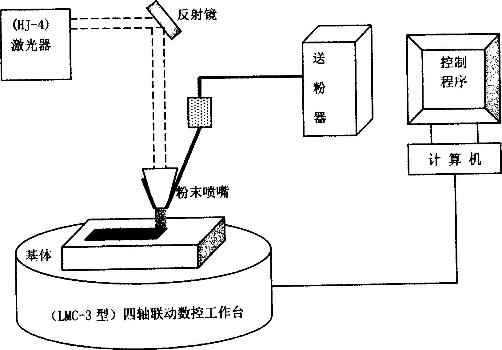
Method used
Image

Examples
Embodiment 1
[0016] Example 1: Sintered 50mm×4mm×40mm thin wall
[0017] The sintering process is: use nickel-copper-tin alloy powder with an average particle size of 100 μm. The laser power is set to 1150W, the defocus distance is 20mm, and the powder feeding speed is 20r / min. Three 50mm×4mm×40mm thin-walled samples were sintered at scanning speeds of 300mm / min, 350mm / min, and 400mm / min, respectively. Generate a 3D CAD model of the thin-walled wall in the computer, 50mm×4mm×40mm, convert the 3D CAD model into 20 2D plane models 50mm×4mm perpendicular to the direction of laser irradiation, and transfer the data of the 2D plane model Convert it into CNC machining commands to control the working process of the laser cladding and sintering molding device. The sintered sample structures are dense, uniform, and free of macro-segregation. Further studies have shown that when the scanning speed is 300 mm / min, the temperature gradient between the laser spot and the forming substrate is large, a...
Embodiment 2
[0018] Example 2: Sintering a thin-walled cylinder of Φ30mm×2mm×40mm
[0019] The sintering process is: use nickel-copper-tin alloy powder with an average particle size of 125 μm. Use slicing software to convert the three-dimensional CAD model into 40 two-dimensional plane models perpendicular to the laser irradiation direction. During the sintering process, the scanning speed is fixed at 350mm / min, the defocus is 20mm, and the powder feeding speed is 20r / min. Under the same conditions, three thin-walled cylindrical samples of Φ30mm×2mm×40mm were sintered with laser powers of 1000W, 1150W and 1300W respectively. The results showed that the sample tissues were relatively dense. When the laser power is 1150W, the sample layer and the interlayer are metallurgically bonded, the structure is the most compact, and no pores and cracks are found.
Embodiment 3
[0020] Embodiment 3: sintering a thin-walled square cylinder of 30mm×30mm×20mm
[0021] The sintering process is: use nickel-copper-tin alloy powder with an average particle size of 150 μm. The 3D CAD model was converted into 10 2D plane models perpendicular to the laser irradiation direction by using slicing software. During the sintering process, the scanning speed was fixed at 350mm / min, the laser power was set at 1150W, and the powder feeding speed was 20r / min. Under the above conditions, three thin-walled square cylinders of 30mm×30mm×20mm were sintered with defocusing amounts of 15mm, 20mm and 25mm, respectively. The results showed that the samples were dense and homogeneous. In comparison, when the defocus amount is 20 mm, the dendrite structure is the most slender, uniform, and grows in the same direction.
PUM
| Property | Measurement | Unit |
|---|---|---|
| The average particle size | aaaaa | aaaaa |
Abstract
Description
Claims
Application Information