Burner with ignition needle protection structure

A technology for protecting structures and burners, applied in burners, gas fuel burners, combustion methods, etc., can solve the problems of ignition needle pollution, ignition failure, explosion of the ceramic outer wall of the ignition needle, etc., to avoid explosion, improve speed and Success rate and effect of prolonging service life

Active Publication Date: 2006-12-27
NINGBO FOTILE KITCHEN WARE CO LTD
View PDF0 Cites 27 Cited by
  • Summary
  • Abstract
  • Description
  • Claims
  • Application Information

AI Technical Summary

Problems solved by technology

Analyzing the cause of the ignition needle failure, it is found that it mainly exists in the following aspects: first, during the cooking process, liquids such as water or oil are directly dripped on the ignition needle, causing the ceramic outer wall of the ignition needle to burst, resulting

Method used


Image

  • Burner with ignition needle protection structure
  • Burner with ignition needle protection structure
  • Burner with ignition needle protection structure

Examples


Embodiment 1

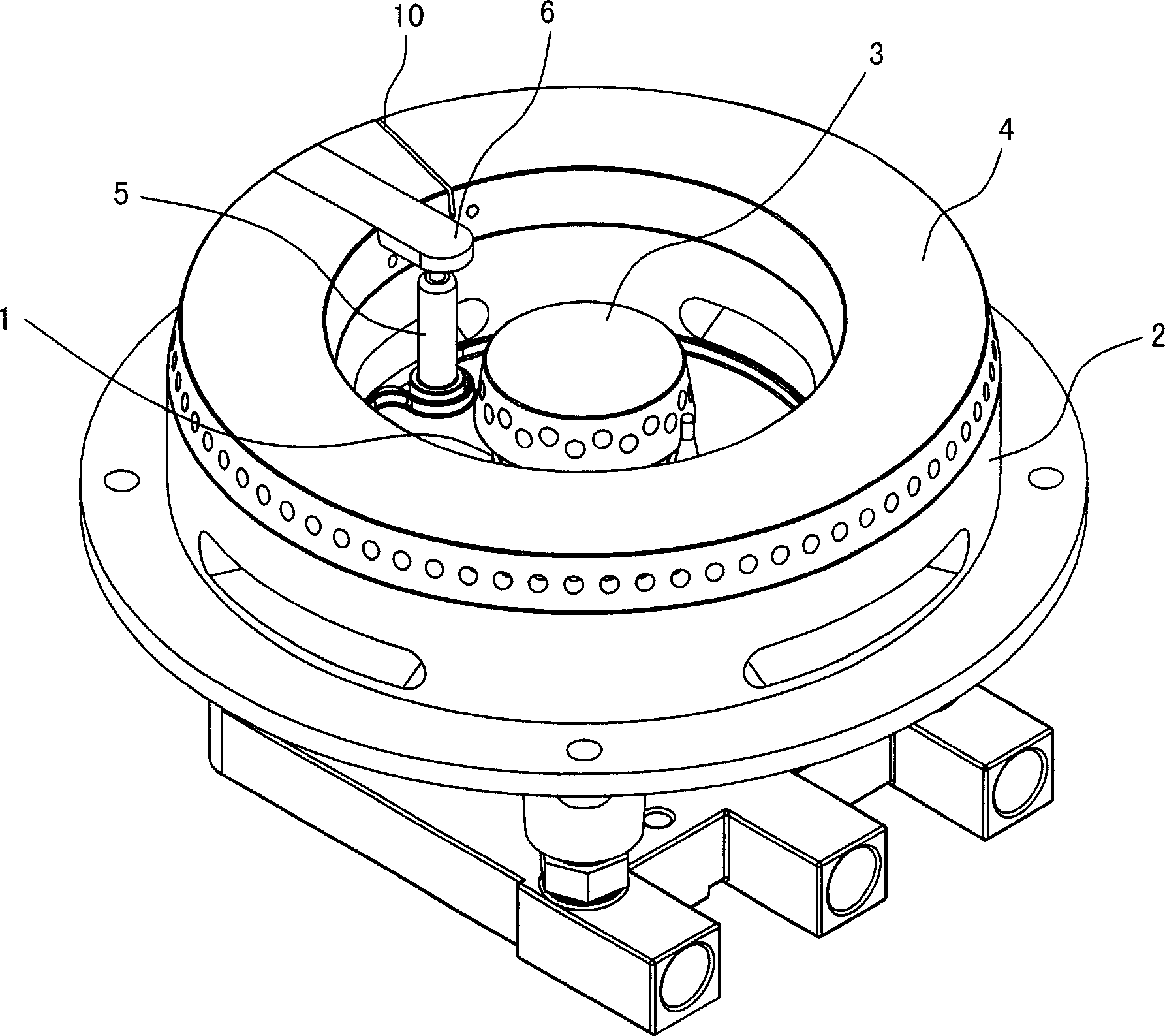
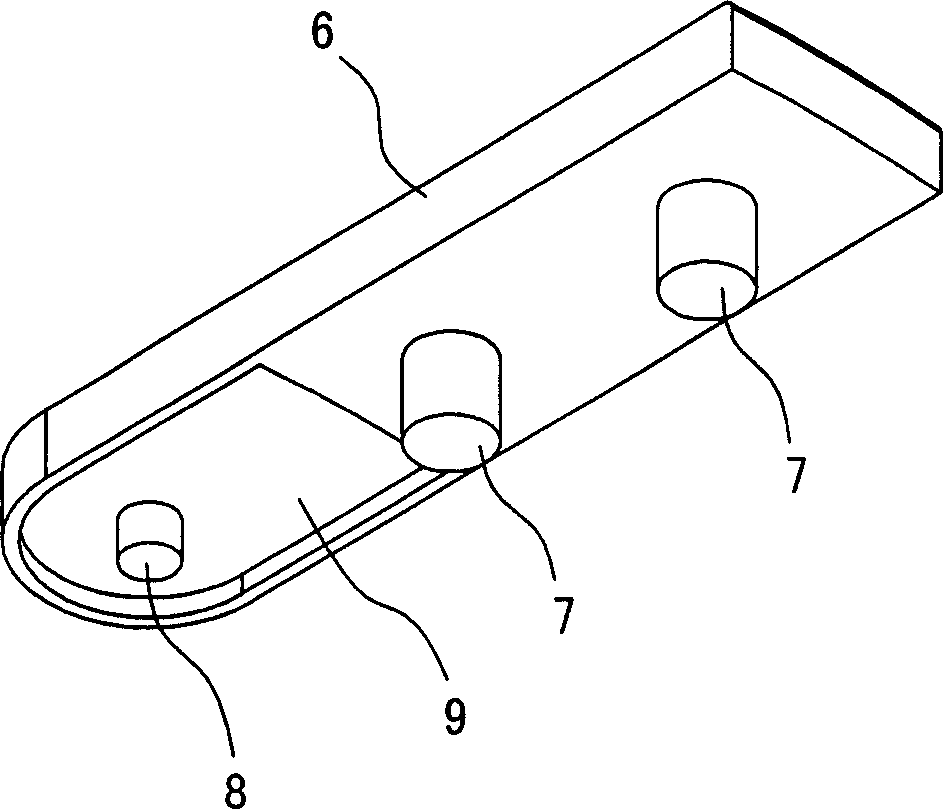
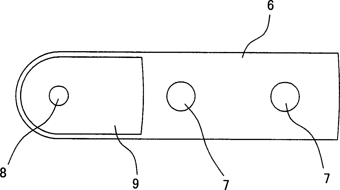
[0031] Such as Figure 1 ~ Figure 4 Shown is a preferred embodiment of the present invention. Such as Figure 1 ~ Figure 4 As shown, the burner with ignition needle protection structure in this embodiment has an inner air mixing chamber 1, an outer ring air mixing chamber 2, an inner ring fire cover 3, an outer ring fire cover 4 and an ignition needle 5, and also has a setting On the block-shaped protective cover 6 above the ignition pin 5, the lower surface of the rear end of the protective cover 6 extends downward with two positioning pins 7, and the lower surface of its front end extends downwards corresponding to the position of the ignition pin 5. The protruding needle 8 is formed with a concave area 9 around the periphery of the protruding needle 8. The outer ring fire cover 4 is provided with a positioning groove adapted to the rear end of the protective cover 6 , and the bottom of the positioning groove is provided with a positioning hole adapted to the positioning p...

Embodiment 2

[0033] Such as Figure 5 ~ Figure 6 shown, and see figure 1 , the burner of this embodiment, the protective cover 6 arranged above the ignition needle 5 is a section of arc-shaped protrusion horizontally extending from the outer ring fire cover 4 to the inside, and the upper surface and the lower surface of the protective cover 6 are both Neat plane.

Embodiment 3

[0035] Such as Figure 7 ~ Figure 8 shown, and see figure 1 For the burner in this embodiment, the protective cover 6 arranged above the ignition pin 5 is a circle of ring-shaped bumps extending horizontally from the outer ring ignition cover 4 to the inside, and the upper surface and the lower surface of the protective cover 6 are both for a neat plane.


PUM


Abstract

The invention relates to a burner with ignite needle protector, which comprises an internal mixing room, an external annular mixing room, an internal annular fire cover, an external annular fire cover and an ignite needle, wherein the invention is characterized in that: a protective cover covering the ignite needle is arranged above the ignite needle; the lower surface of protective cover has protrude needle at the position relative to the ignite needle; said protective cover can effectively avoid exploding ignite needle, and avoid ignite needle being polluted by dropped oil, to prolong its service life. The protrude needle and the ignite needle can both ignite, to improve the ignite speed and success rate.

Description

technical field [0001] The invention relates to an improvement of a burner for a gas stove, in particular to a burner with an ignition needle protection structure. Background technique [0002] The burner used in household gas stoves generally has an inner gas mixing chamber, an outer ring gas mixing chamber, an inner ring fire cover, an outer ring fire cover and an ignition needle. Wherein, the ignition pin is usually installed at the position between the inner ring fire cover and the outer ring fire cover. In addition, there is also the situation that the ignition needle is installed outside the outer ring fire cover. However, no matter where the ignition pin is installed, the ignition pin on the existing burner is completely exposed and can be seen directly. In actual use, it is found that although the proportion of ignition needle failure in the total failure of the burner is not very large, it cannot be ignored. Analyzing the cause of the ignition needle failure, it i...

Claims


Application Information

Patent Timeline
IPC IPC(8): F23D14/76
Inventor 徐慧蔡国汉胡杰
Owner NINGBO FOTILE KITCHEN WARE CO LTD
Why Eureka
Try Eureka