
Method for generating signal flow graph

A signal flow graph and functional unit technology, applied in the field of network communication, can solve problems such as large differences in layout and large impact on signal flow graphs

Inactive Publication Date: 2006-12-27
HUAWEI TECH CO LTD
View PDF0 Cites 3 Cited by
  • Summary
  • Abstract
  • Description
  • Claims
  • Application Information

AI Technical Summary

Problems solved by technology

[0015] The purpose of the present invention is to provide a method for generating a signal flow diagram to solve the problem that the signal flow diagram in the prior art signal flow arrangement algorithm is very different from the actual functional unit and fiber cable arrangement, and in the new The problem of excessive impact on the existing signal flow diagram when adding functional units and / or cables

Method used


Image

  • Method for generating signal flow graph
  • Method for generating signal flow graph
  • Method for generating signal flow graph

Examples


Embodiment Construction

[0037] In order to make the object, technical solution and advantages of the present invention more clearly, the present invention will be further described in detail below in conjunction with the accompanying drawings and specific embodiments.

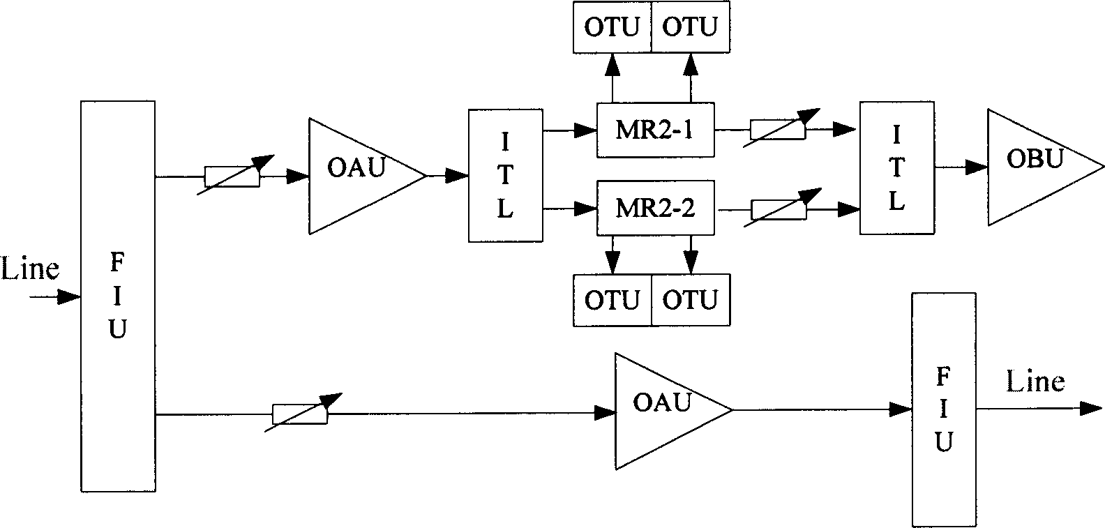
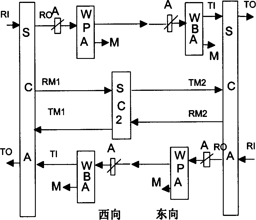
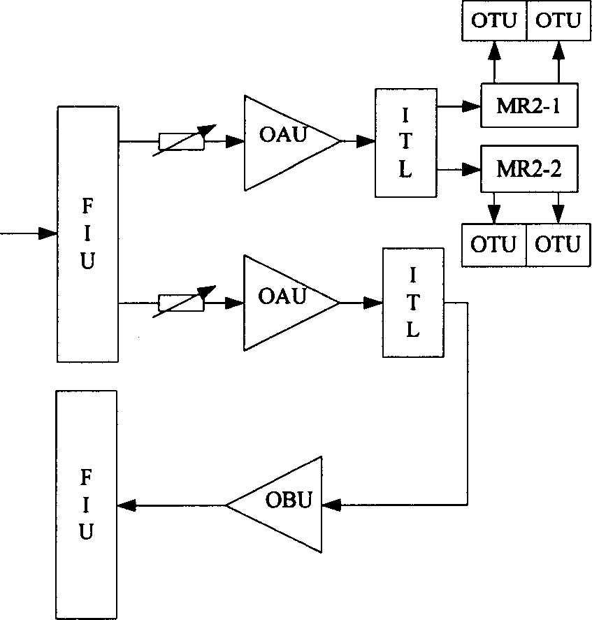
[0038] Aiming at the problem that the signal flow graph existing in the current signal flow arrangement algorithm in the prior art is very different from the actual functional unit and fiber cable arrangement, and when adding new functional units and / or fibers and cables to the existing signal flow For the problem of excessive graph impact, this invention proposes a method for generating signal flow graphs, that is, a two-step adjustment mechanism that first arranges regularly and then adjusts according to internal fiber and cable information. The advantages of the two schemes of path arrangement make the arrangement of the signal flow diagram and the engineering system Figure 1 It can clearly see the signal flow direction inside the ...


PUM


Abstract

The related method for signal flow graph comprises: taking regular distribution firstly, then adjusting according to inner cable information. This invention combines the advantages of rule and longest path distributions, eliminates effect from new added unit to original graph, and can ensure the graph integrality.

Description

technical field [0001] The invention relates to network communication technology, in particular to a method for generating a signal flow graph in the field of optical communication technology. Background technique [0002] WDM (Wavelength Division Multiplexing, wavelength division multiplexing) equipment can generally be divided into OTM (Optical Terminal Multiplexer, optical terminal multiplexing equipment), OLA (Optical Line Amplifier, optical line amplification equipment), OADM (Optical Add / DropMultiplexer, Optical add-drop multiplexing equipment), REG (Regeneration, electrical relay equipment), and different types of equipment have different internal signal flows. [0003] Taking OTM as an example, in the sending direction, OTM multiplexes STM-16 signals with a wavelength of λ1~λ16 (or λ32) into a WDM main channel through a multiplexer, then optically amplifies it, and adds a signal with a wavelength of λs Optical Supervisory Channel. In the receiving direction, the OT...

Claims


Application Information

Patent Timeline
IPC IPC(8): H04Q3/00H04B10/20H04B10/27
Inventor 倪乔力
Owner HUAWEI TECH CO LTD
Learn More