Cooling process and device for a steel sheet

A technology of cooling device and steel strip, applied in the direction of quenching device, furnace, furnace type, etc., can solve the problem of low cooling rate and achieve uniform spraying speed

Active Publication Date: 2006-12-27
ARCELOR FRANCE (FR)
View PDF4 Cites 4 Cited by
  • Summary
  • Abstract
  • Description
  • Claims
  • Application Information

AI Technical Summary

Problems solved by technology

Although this method is characterized by a particularly uniform cooling effect with a constant heat transfer coefficient regardless of the condition of the production line, it also has some limitations
[0021] [21] First, the achievable cooling rate is relatively low, that is, for a 1 mm thick steel strip, the cooling rate is about 50 °C / s
[0030] [30] Although various approach schemes have been proposed so far, how to obtain high thermal performance while performing rapid cooling with a liquid device and at the same time have good flatness after cooling remains a great challenge.

Method used


Image

  • Cooling process and device for a steel sheet
  • Cooling process and device for a steel sheet
  • Cooling process and device for a steel sheet

Examples


Embodiment Construction

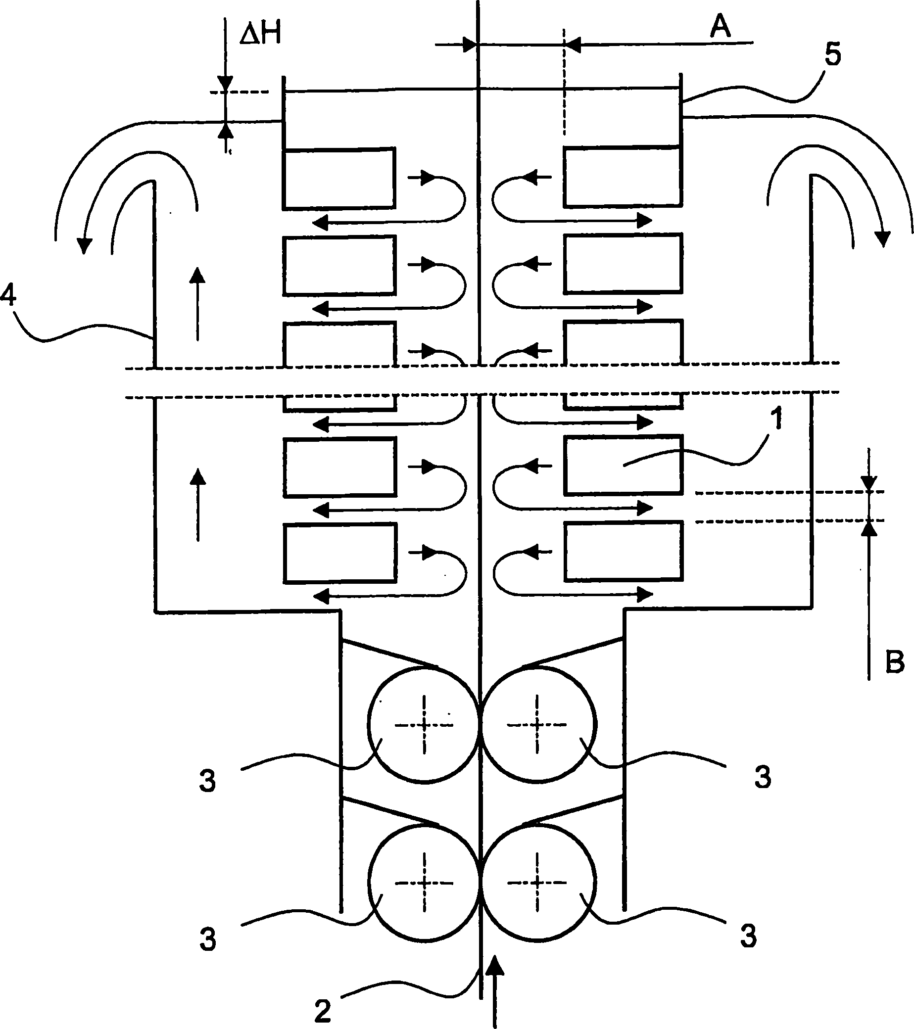
[0068] [65] If figure 1 As shown, the cooling device includes a group of pipes 1, which are called "workbench" or "cooling workbench", and these pipes are symmetrically arranged on both sides of the steel strip to be cooled. These tables are immersed in cooling fluid and are supplied with cooling fluid in the transverse direction. Their cross-section is preferably rectangular. In the further description of the invention, the words "pipe" and "table" are used without distinction.

[0069] [66] The immersion of the workbench into the fluid is achieved by means of a sealing system located in the lower part of the device, which allows the passage of the steel belt 2 and creates a maximum load loss in order to direct the cooling fluid to the bottom of the housing Leakage is limited to a minimum. In the present application, the sealing system consists of two pairs of roller bodies 3 which are pressed against the steel belt and positioned symmetrically with respect to the steel be...


PUM

PropertyMeasurementUnit
thicknessaaaaaaaaaa

Abstract

The invention relates to a cooling device for implementing a tempering operation of a steel strip, comprising a weir (4) in which a number of tubes (1) are completely immersed, which are, in essence, vertically stacked and arranged symmetrically on both sides of the strip (2) along this strip, and which discharge, in the form of essentially horizontal turbulent jets, a cooling fluid across a slot or a number of holes. A sealing memeber is installed on the lower part. Any two successive tubes (1), which are situated on the same size of the strip (2), are separated by the same gap (B) for all the tubes (1) for evacuating the cooling fluid. The gap (B) is set to a given specific flow rate value of the fluid in order to minimize the loss of load in the evacuation channels corresponding to said gap (B).

Description

technical field [0001] [01] The invention relates to a device for cooling a steel strip using a continuous annealing method. In particular, this cooling operation is performed by means of submerged water jets. The cooling operation may be performed after a first cooling operation performed in a boiling water tank. Background technique [0002] [02] Continuous annealing is a thermochemical treatment that is performed after the cold rolling process is performed on the steel strip. By metal "strip" is meant a metal article which, when cut, forms sheet metal which is used, inter alia, to make the bodies of automobiles, the frames of household electrical appliances, and the like. [0003] [03] The method of continuous annealing consists in passing the steel strip through a heat treatment furnace in which the steel strip is subjected to controlled heating and cooling. In a continuous annealing furnace, the steel strip moves vertically along a series of sequential ascending and ...

Claims


Application Information

Patent Timeline
Patent Type & Authority Applications(China)
IPC IPC(8): C21D9/573C21D9/00C21D9/56C21D1/63C21D1/667
CPCC21D9/5735C21D1/63C21D1/667C21D9/573C21D9/00C21D9/56
Inventor S·勒孔特A·富阿尔热D·布克格内奥
Owner ARCELOR FRANCE (FR)
Why Eureka
Try Eureka