Heated window pane

A glass plate and heating wire technology, which is applied in ohmic resistance heating, transparent/reflective heating devices, glass/slag layered products, etc., can solve the problems of unreachable length of heating wire, increased cost, and the same

Inactive Publication Date: 2006-12-27
彼特·堡姆勒
View PDF2 Cites 16 Cited by
  • Summary
  • Abstract
  • Description
  • Claims
  • Application Information

AI Technical Summary

Problems solved by technology

In this way, the length of the heating wire can hardly be exactly the same in fact.
Furthermore, to make the heating wire form an insulation through the upper contact busbar to the lower contact busbar, this will increase the cost technically.

Method used


Image

  • Heated window pane
  • Heated window pane

Examples


Embodiment Construction

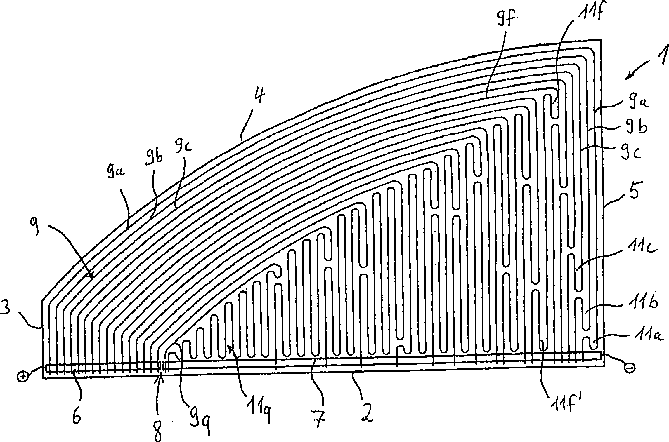
[0022] This is a laminated glass pane with a plastic foil (not visible) between two pane elements. Attached to the plastic foil are contact busbars 6, 7 and a bundle of heating wires 9.

[0023] Arranged along the bottom edge 2 are a contact busbar 6 to be connected to the positive pole of the DC power supply and a contact busbar 7 to be connected to the negative pole of the DC power supply (not shown), which are separated from each other by a gap 8 .

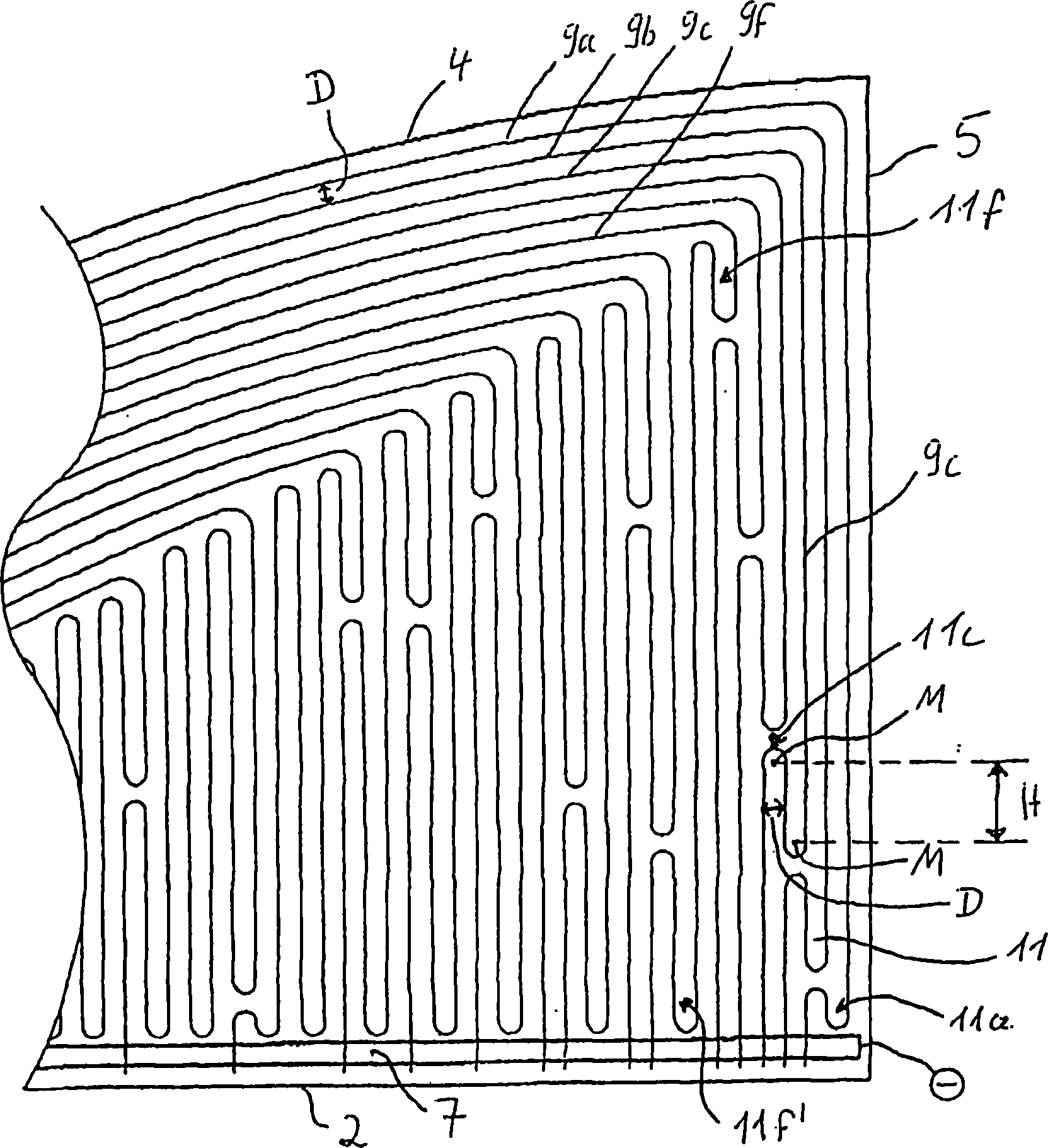
[0024] An outermost heating wire 9a electrically contacts the end of the bus bar 6 facing the front edge 3, and the heating wire 9a moves along the front edge 3, the upper edge 4 and the rear edge 5 to the rear facing side of the contact bus bar 7 The outer end of the edge 5 is in electrical contact with the contact busbar 7 . Next to the outermost heating wire 9a, a certain interval D is the second outermost heating wire 9b. According to the type of heating wire used and the required heating power density, the spacing D can b...


PUM

PropertyMeasurementUnit
strengthaaaaaaaaaa

Abstract

Disclosed is a heated window pane (1), particularly for side windows of vehicles, comprising two differently polarized contact busbars (6, 7) which extend essentially parallel to each other in the longitudinal direction thereof as well as parallel to a bottom edge (2) of the heated window pane (1), and a bunch of heating filaments (9) that electrically contact the contact busbars (6, 7). The inventive window pane (1) is characterized in that the contact busbars (6, 7) are arranged substantially along one line in the longitudinal direction thereof while the heating filaments (9) have essentially the same length such that uniform heating of the entire window pane (1) can be ensured. The heating filaments (9) can be made to have the same length by configuring compensation loops (11) and / or varying the amplitude of a heating filament (9) that is disposed in a wavy shape.

Description

technical field [0001] The invention relates to a heatable glass pane comprising two contact bars of different polarity arranged longitudinally essentially parallel to each other and parallel to its bottom edge and a bundle electrically contacting the two contact bars (Kontaktsammelschiene) heating wire. Background technique [0002] One such glass pane is known from DE 101 26 869 . This patent discloses an electrically heated glass pane, in which two contact busbars arranged parallel to one another at different distances from the base and thus transversely to its longitudinal direction are arranged one above the other. The heating wire starts from the upper contact bus bar, forms multiple loops, and then leads over the upper contact bus bar to the lower contact bus bar, wherein, the heating wire located at the intersection with the upper contact bus bar intersects with the The busbars are electrically insulated. The arrangement of the two contact busbars on the edge of t...

Claims


Application Information

Patent Timeline
Patent Type & Authority Applications(China)
IPC IPC(8): H05B3/84
CPCH05B2203/002H05B2203/005H05B3/84B32B17/10385C03C17/00
Inventor 彼特·堡姆勒
Owner 彼特·堡姆勒
Why Eureka
Try Eureka