Electrothermally defogging oral reflector

A mirror, oral technology, applied in the direction of oral mirror, medical science, diagnosis, etc., can solve problems such as easy fogging, and achieve the effect of simple structure and convenient use

Inactive Publication Date: 2007-01-03
SHANGHAI LASER MEDICAL INSTR CO LTD
View PDF0 Cites 3 Cited by
  • Summary
  • Abstract
  • Description
  • Claims
  • Application Information

AI Technical Summary

Problems solved by technology

[0003] The object of the present invention is to provide a kind of electrothermal defogging oral mirror, said this electrothermal de

Method used


Image

  • Electrothermally defogging oral reflector

Examples


Embodiment Construction

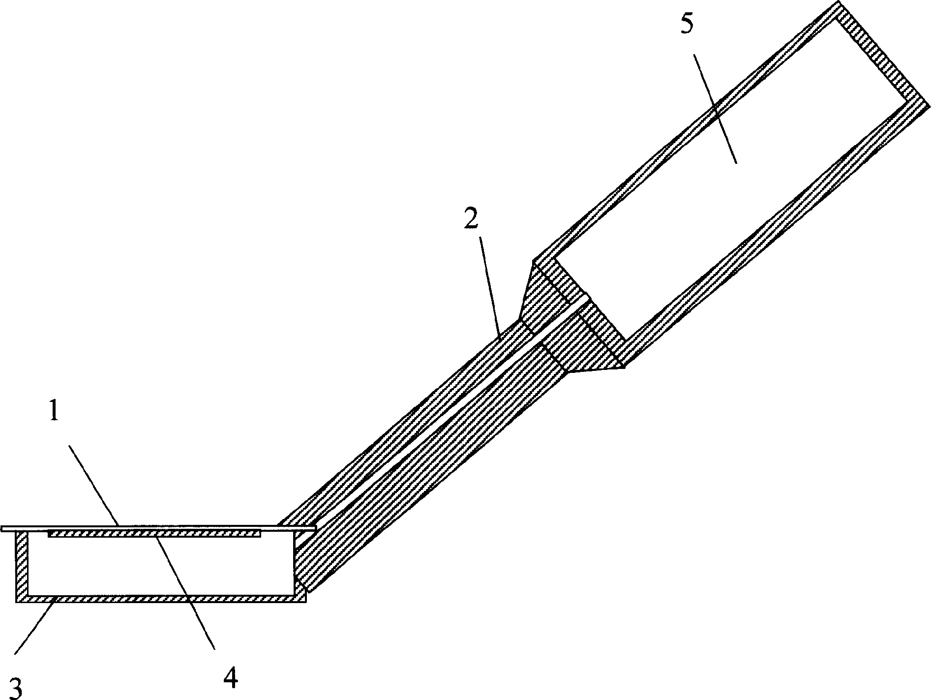
[0009] Such as figure 1 As shown, the oral reflector for electrothermal defogging of the present invention is composed of a circular reflector 1 and a handle 2, wherein a base 3 is provided at the front end of the handle 2, and the reflector 1 is fixedly arranged On the upper end of the base 3, the bottom side of the reflector 1 is fixedly provided with an electric heating element 4, and the handle 2 is provided with a battery compartment 5, and the battery compartment 5 is provided with The battery contact piece, the battery contact piece is connected to the electric heating element 4 through a wire and a switch, the axial direction of the handle 2 and the mirror surface of the reflector 1 form between 110 degrees and 160 degrees angle between.

[0010] Further, the electric heating element 4 is composed of resistance wires, and the resistance wires are spirally attached to the bottom side of the reflector 1 .


PUM


Abstract

The electrothermally defogging oral reflector consists of one reflector and one handle. The handle has one pedestal set in the front end for the reflector to be set on, and there are one electrothermal element fixed in the pedestal, one battery compartment set inside the handle, and one switch connected to the electrothermal element. The handle axis and the mirror of the reflector are in one angle of 110-160 deg. The electrothermal element constituted of spiral resistive wire in the bottom of the pedestal heats the reflector to temperature higher than that of air inside oral cavity, so as to avoid vapor condensation in the mirror and to maintain clear mirror. The present invention has simple structure and convenient use.

Description

Technical field: [0001] The invention relates to medical equipment, in particular to a medical auxiliary observation device, in particular to a dental reflector, in particular to an electrothermal defogging oral reflector. Background technique: [0002] In the prior art, a dentist oral mirror is composed of a reflector and a handle, the reflector is arranged at the front end of the handle, and the mirror surface of the reflector forms an angle between 110° and 160° with the handle. When in use, the reflector extends into the patient's mouth, and the dentist adjusts the angle of the reflector to reflect the lighting on the treatment chair to the teeth that need to be inspected and treated, and then observe. Due to the high humidity of the gas in the oral cavity, the temperature is usually higher than the room temperature, and the mirror surface of the mirror is usually equal to the room temperature. Therefore, the water vapor in the oral cavity is easy to condense on the mirr...

Claims


Application Information

Patent Timeline
IPC IPC(8): A61B1/253
Inventor 曾平
Owner SHANGHAI LASER MEDICAL INSTR CO LTD
Why Eureka
Try Eureka