Aerator

A technology of aeration equipment and aeration device, applied in water aeration, sustainable biological treatment, water/sludge/sewage treatment, etc., can solve the problems of power resource consumption and cost increase, and increase the aeration range , increase the effect of convection and stirring

Inactive Publication Date: 2007-01-03
蔡荣锋
View PDF0 Cites 5 Cited by
  • Summary
  • Abstract
  • Description
  • Claims
  • Application Information

AI Technical Summary

Problems solved by technology

In this way, it not only consumes considerable power resources, but also increases the cost of setting up multiple traditional waterwheels.

Method used


Image

  • Aerator
  • Aerator
  • Aerator

Examples


Embodiment Construction

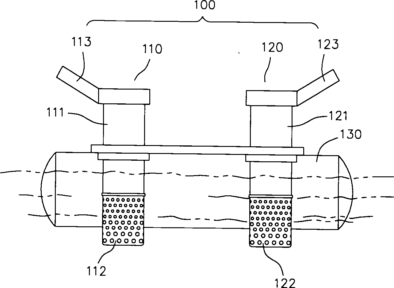
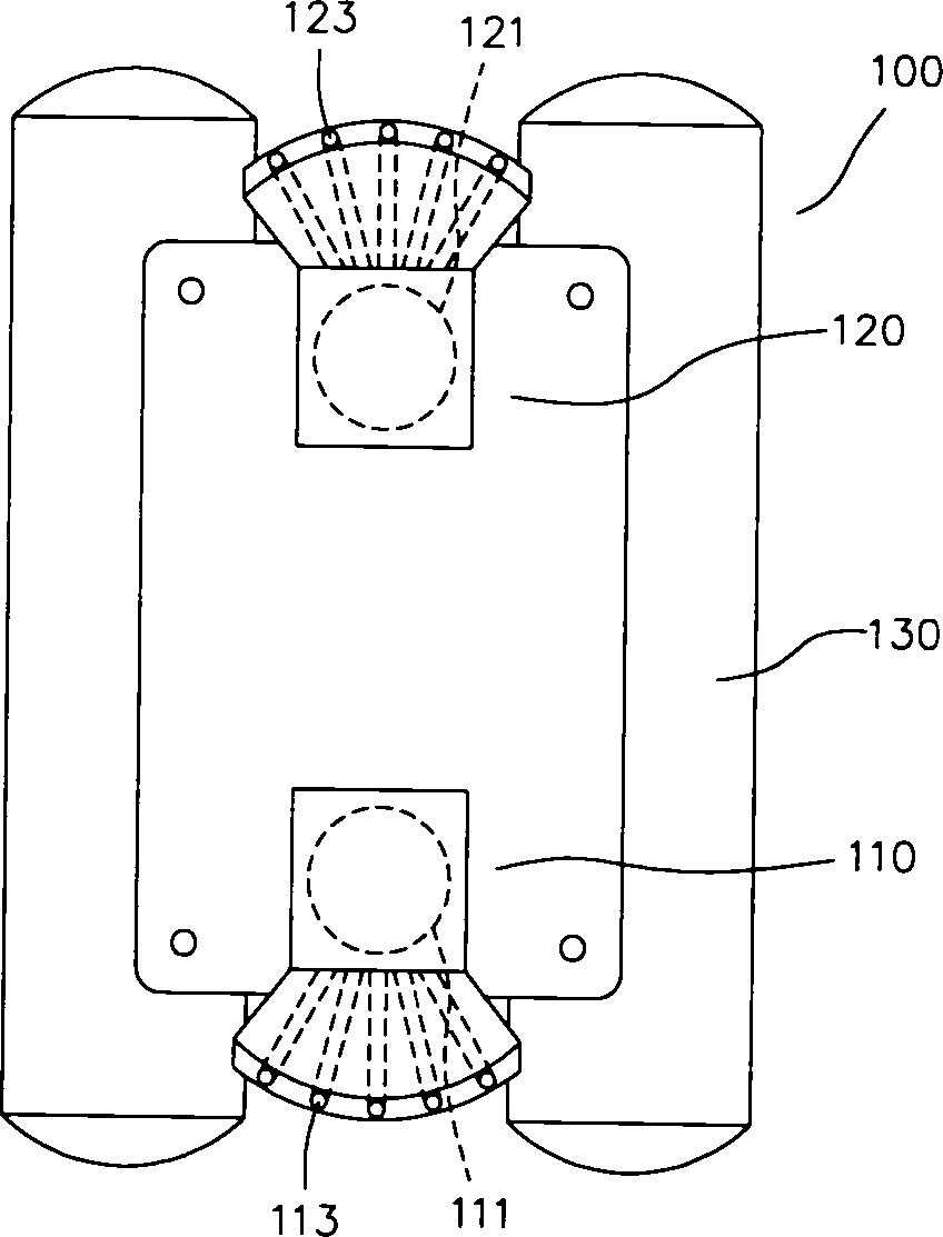
[0047] Please refer to figure 1 with figure 2 As shown, it is a side view and a top view of an aeration device according to a preferred embodiment of the present invention. The plurality of aeration devices of the aeration equipment 100 of the present invention is firstly taken as an example of two sets of aeration devices.

[0048] The aeration device 100 includes a first aeration device 110 , a second aeration device 120 and a floating body 130 . Wherein, the first aeration device 110 and the second aeration device 120 are installed on the floating body 130 at the same time, and the floating body 130 can float on a water surface.

[0049]The first aeration device 110 has a water drawing device 111 which is a water pump; the water inlet is provided with a filter 112 , and the water outlet is provided with a spray port 113 . The injection ports 113 are outwardly and upwardly inclined by 15° to 50°, and may be distributed radially in several lines.

[0050] The second aera...


PUM


Abstract

The aerator includes at least one floating body, several aerating units and one controller. The aerating units assembled on the floating body spray, atomize or aerate sucked water. The controller controls the aerating units to generate one first push force for the aerator to move in one first direction and generate one second push force for the aerator to move in one second direction.

Description

technical field [0001] The present invention relates to an aeration device, and in particular to a method for spraying water mist or spraying a water-air mixture through a spray port to generate a reaction force, control the movement of the aeration device, and achieve the aeration effect of a large area of ​​water , and is also used as aeration equipment for entertainment, advertising, landscaping or installation art. Background technique [0002] Aquaculture ponds or fish farms maintain the concentration of dissolved oxygen (DO) through aeration devices to maintain the respiration of aquaculture, aquatic organisms and microorganisms, which is a necessary factor for stabilizing water quality and maintaining the ecological balance of fish ponds. Microorganisms (decomposers) must absorb dissolved oxygen from water to digest excess organic matter and perform nitrification to convert highly toxic ammonia nitrogen into weakly toxic nitrite nitrogen (NO2) or nitrate nitrogen (NO3...

Claims


Application Information

Patent Timeline
Patent Type & Authority Applications(China)
IPC IPC(8): C02F7/00
CPCY02W10/10
Inventor 蔡荣锋
Owner 蔡荣锋
Why Eureka
Try Eureka