Catalytic conversion method and apparatus
A catalytic conversion method and catalyst technology, applied in the field of catalytic conversion of petroleum hydrocarbons, can solve problems such as poor product selectivity, unfavorable regeneration, large temperature difference in the reaction process, etc., and achieve low contact temperature, increased octane number, and gasoline olefin content Reduced effect
- Summary
- Abstract
- Description
- Claims
- Application Information
AI Technical Summary
Problems solved by technology
Method used
Image
Examples
Embodiment 1
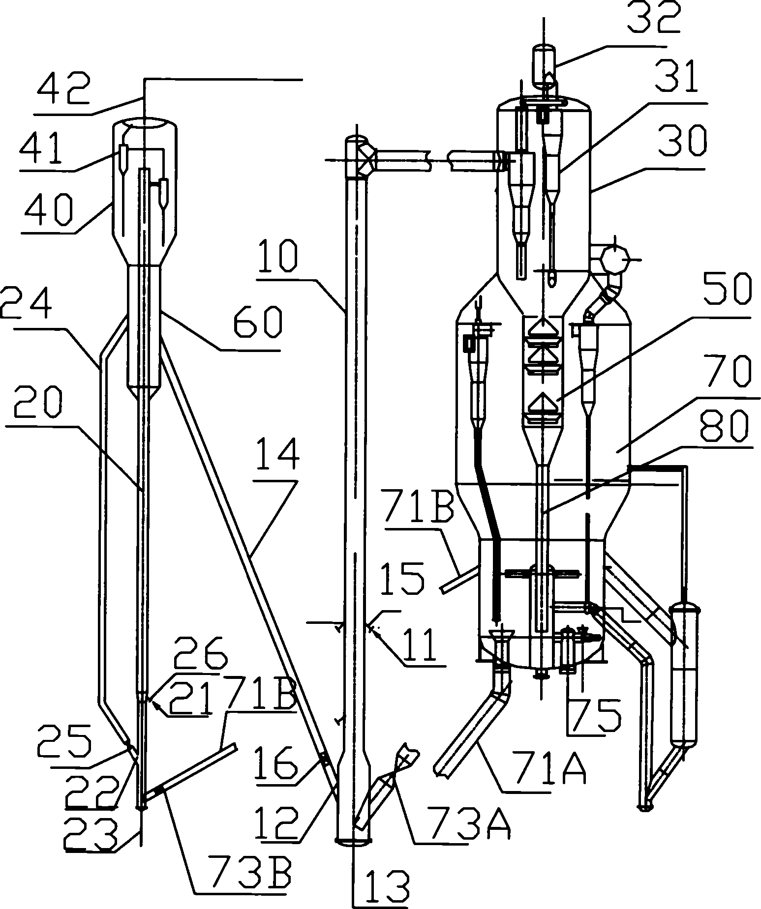
[0033] Example 1. The reaction materials are: pipeline transportation of heavy oil at atmospheric pressure, 100t / h heavy oil, gasoline feedstock is heavy oil reaction self-produced gasoline; heavy oil is preheated at 220°C, gasoline is at 40°C; the reactor is in the form of a riser; the heavy oil is divided into four routes After entering the riser, the gasoline enters the reactor in two ways; the reaction temperature of heavy oil is 500°C, and the reaction time is 2.5s; the reaction temperature of gasoline is 430°C, and the reaction time is 3s; The catalyst temperature is 550°C; the regeneration temperature is 690°C; in this embodiment, all the catalyst after the gasoline reaction enters the bottom of the heavy oil riser; the catalyst after the gasoline reaction enters the heavy oil riser after being stripped.
[0034] This embodiment uses the device see figure 1 . In this device, beside the heavy oil reactor 10 of the heavy oil reaction-regeneration unit, a gasoline reactor...
Embodiment 2
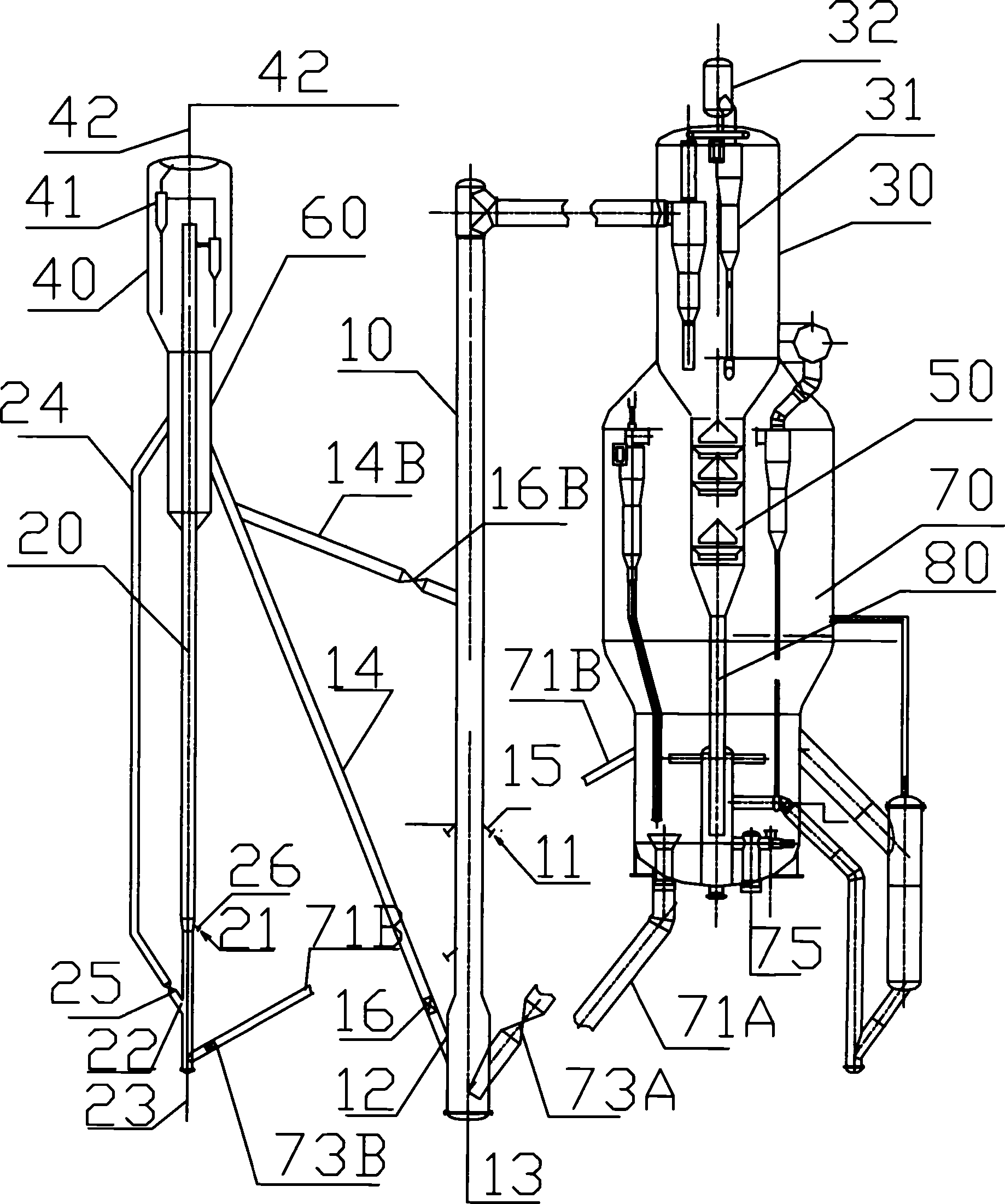
[0037] Embodiment 2, the reaction material is: Daqing atmospheric heavy oil, 100t / h heavy oil, gasoline feedstock is heavy oil reaction self-produced gasoline; heavy oil preheating 220 ℃, gasoline 40 ℃; heavy oil reactor is riser form, gasoline reactor is The gasification section of the riser and the fluidized bed are connected in series; the heavy oil enters the riser in four ways, and the gasoline enters the reactor in two ways; the reaction temperature of heavy oil is 500°C, and the reaction time is 2.5s; the reaction temperature of gasoline is 400°C, and the reaction time is 6s, of which The residence time of gasoline in the gasification section is 0.5s, the residence time in the middle fluidized bed is 4s, and the residence time in the riser above the fluidized bed is 1.5s; the superficial flow velocity of oil and gas in the fluidized bed is 1.5m / s; The catalyst mixing temperature before the tube reaction is 620°C, and the catalyst temperature before the reaction in the ga...
Embodiment 3
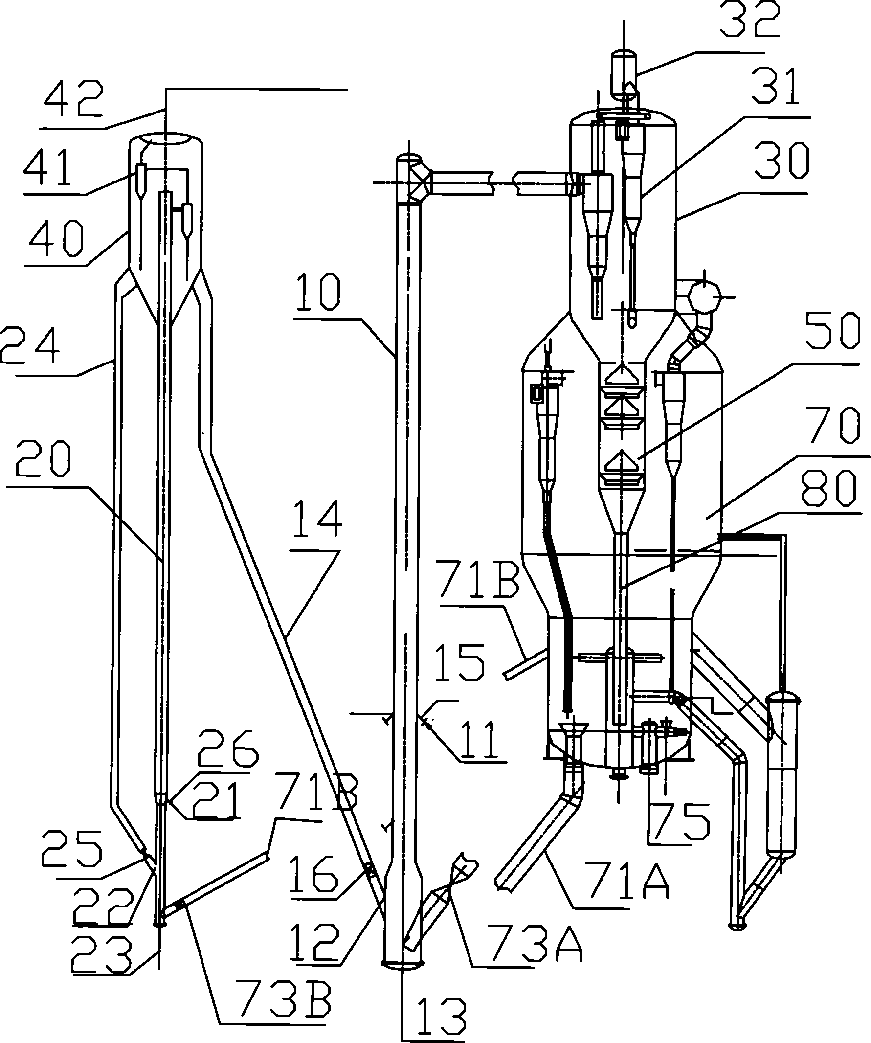
[0041] Embodiment 3. In the device of this embodiment, the upper end of the catalyst delivery pipe 14 is directly connected to the lower part of the gasoline reaction settler 40 . Others are the same as embodiment 1.
PUM
 Abstract
Description
Claims
Application Information
 - R&D
- Intellectual Property
- Life Sciences
- Materials
- Tech Scout
- Unparalleled Data Quality
- Higher Quality Content
- 60% Fewer Hallucinations
Browse by: Latest US Patents, China's latest patents, Technical Efficacy Thesaurus, Application Domain, Technology Topic, Popular Technical Reports.
© 2025 PatSnap. All rights reserved.Legal|Privacy policy|Modern Slavery Act Transparency Statement|Sitemap|About US| Contact US: help@patsnap.com


