Air conditioner matched pipe fixing structure

A fixed structure, air conditioner technology, applied in air conditioning systems, space heating and ventilation, space heating and ventilation details, etc., can solve the problems of refrigerant piping damage, complicated finishing work, noise, etc., to reduce noise and clean up work easy effect

Inactive Publication Date: 2007-01-03
LG ELECTRONICS (TIANJIN) APPLIANCES CO LTD
View PDF0 Cites 3 Cited by
  • Summary
  • Abstract
  • Description
  • Claims
  • Application Information

AI Technical Summary

Problems solved by technology

Since the refrigerant pipes 31 and 32 connected to the heat exchanger 30 are located in front of the air supply assembly 20, the arrangement of the refrigerant pipes 31 and 32 becomes complicated.
Not only that, when the refrigerant pipes 31, 32 vibrate, the refrigerant pipes 31, 32 will collide with the air supply assembly 20, resulting in damage to the refrigerant pipes 31, 32 and the generation of noise.

Method used


Image

  • Air conditioner matched pipe fixing structure
  • Air conditioner matched pipe fixing structure
  • Air conditioner matched pipe fixing structure

Examples


Embodiment Construction

[0068] The pipe fixing structure of the air conditioner of the present invention will be further described in detail below in conjunction with the accompanying drawings and specific embodiments:

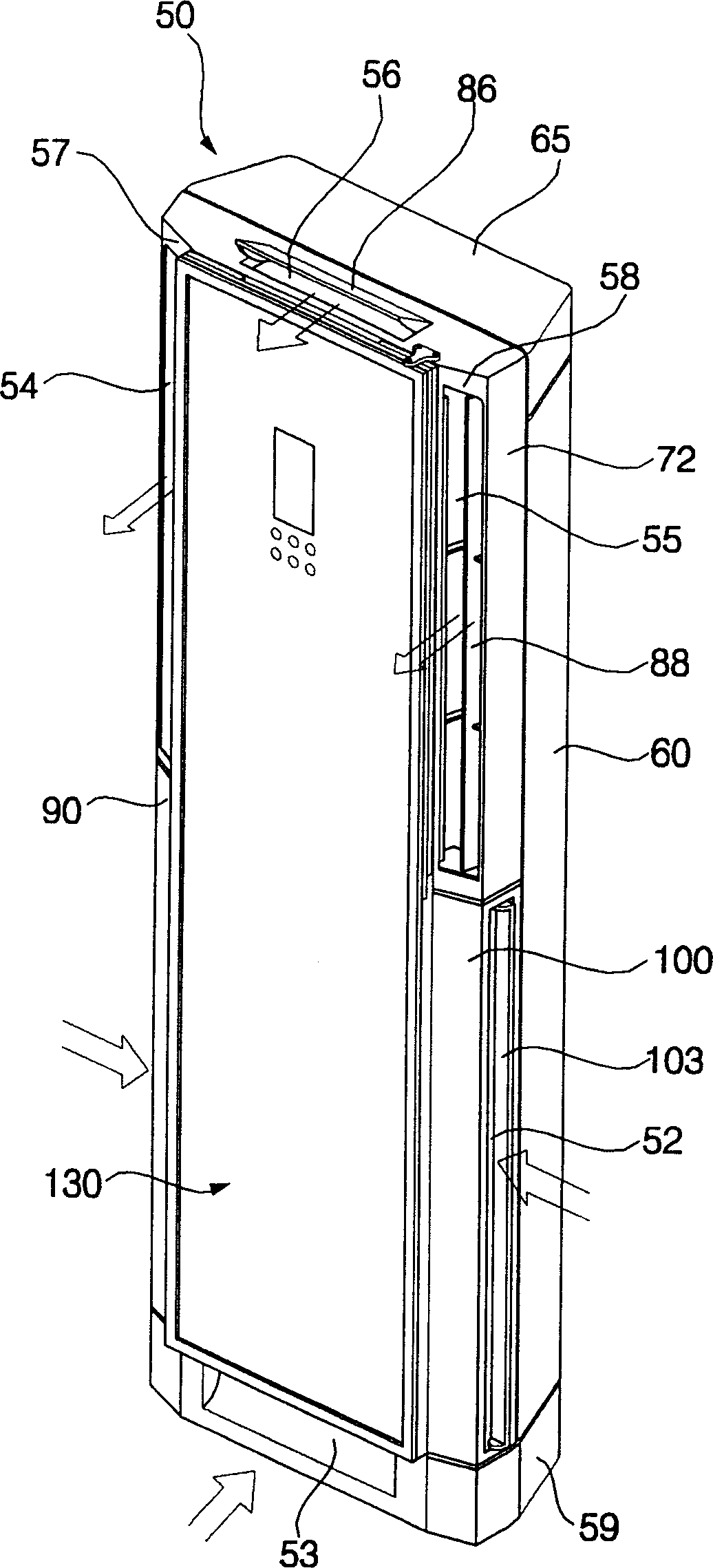
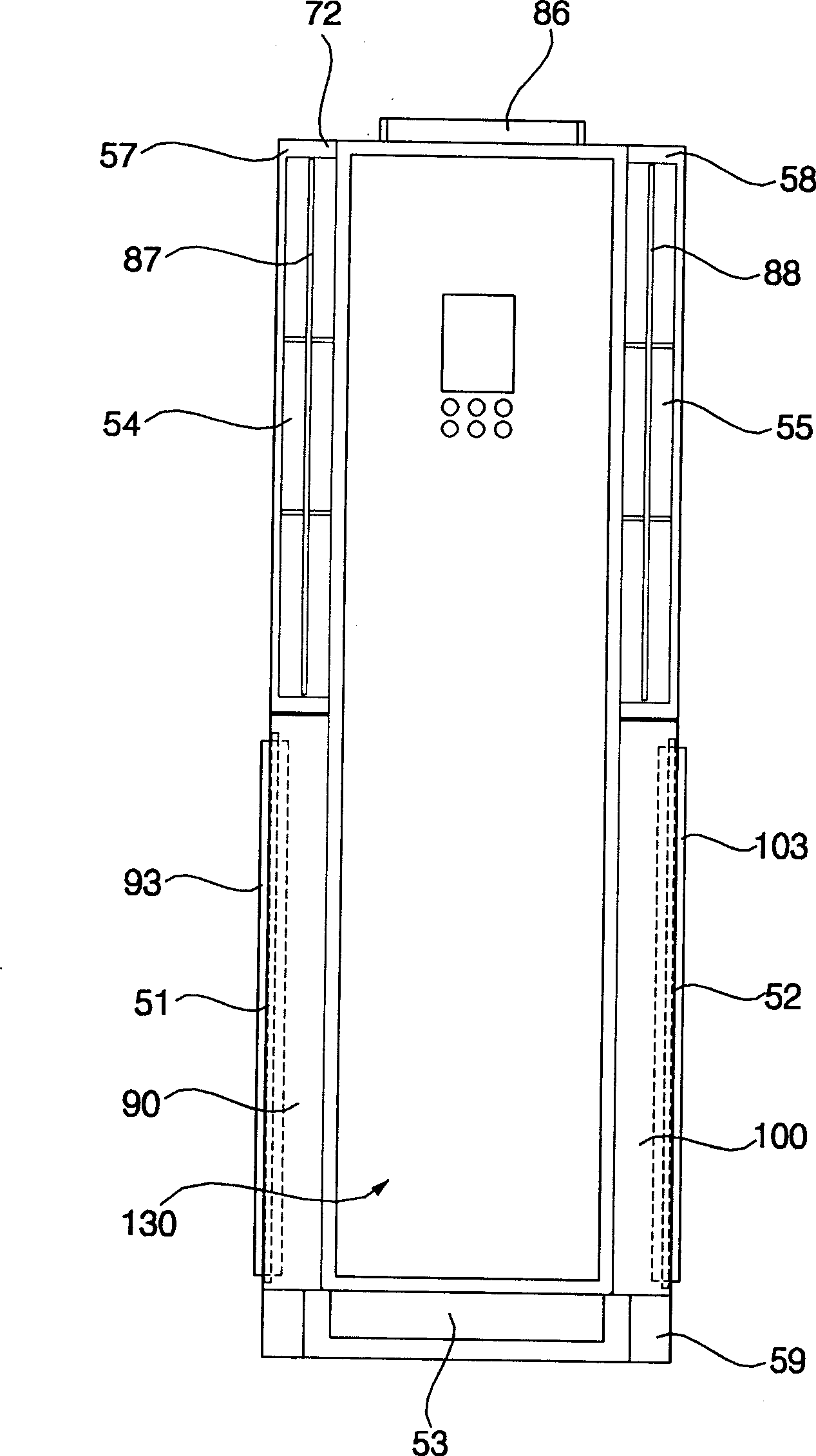
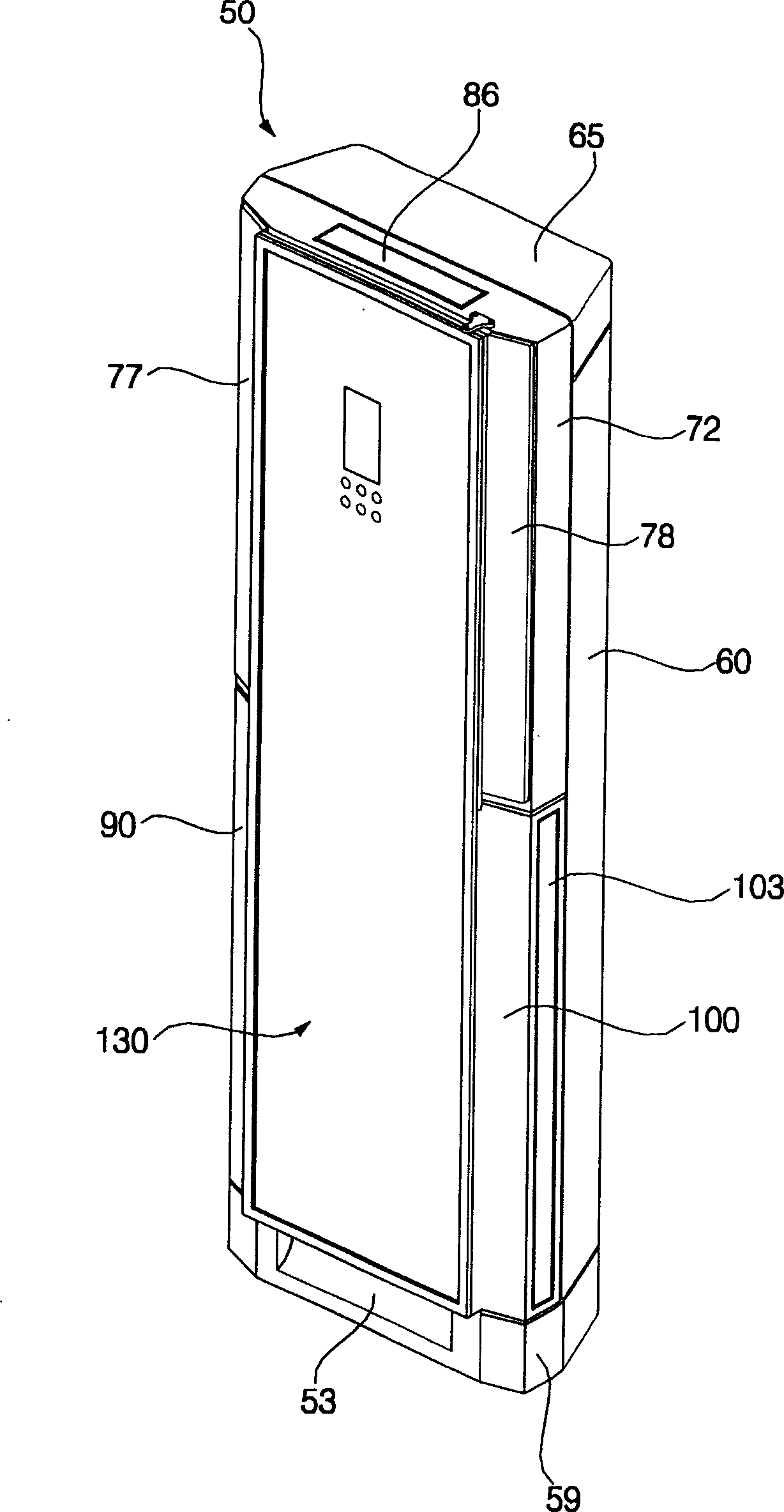
[0069] figure 1 It is a perspective view of an embodiment of an air conditioner to which the pipe fixing structure of the present invention is applied. figure 2 for figure 1 Front view of the air conditioner shown. image 3 for figure 1 The shown perspective view of the air conditioner stopped. Figure 4 for figure 1 An exploded perspective view of the air conditioner shown. Figure 5 for figure 1 Cutaway view of the air conditioner shown.

[0070] Such as Figure 1 to Figure 5 As shown, the present invention is applicable to an embodiment of an air conditioner with a fixed piping structure, and its specific composition is described as follows: suction ports 51, 52, 53 are formed on the lower part of the main body 50 forming the appearance of the air conditioner, and th...


PUM


Abstract

An air conditioner fitting pipe fixing structure comprises a main body, a heat exchanger, a blowing assembly and a fitting pipe water. The heat exchanger and the blowing assembly are holding in the main body and the fitting pipe cover is firm-jointed with the refrigerant fitting pipe of the heat exchanger. The blowing assembly includes a fan housing holding a blowing fan and a fan motor. The fitting cover including a cover part and a connecting part is connected with the fan housing.

Description

technical field [0001] The present invention relates to a pipe fixing structure of an air conditioner, in particular to a pipe fixing structure of an air conditioner which uses a pipe cover to fix refrigerant pipes to an air supply assembly Background technique [0002] The air conditioner in the prior art can bring a more comfortable indoor environment to the user. That is, the air conditioner is capable of cooling / warming a room or purifying polluted indoor air. The working principle of the air conditioner is described as follows: After the air conditioner inhales relatively high-temperature indoor air, it makes the inhaled high-temperature air exchange heat with the refrigerant in a low-temperature state, turning it into low-temperature air, and then discharges the low-temperature air back into the room , and then reduce the indoor temperature by repeating the above process. Alternatively, the room is warmed by the reverse procedure of the above procedure. In detail, a...

Claims


Application Information

Patent Timeline
IPC IPC(8): F24F1/00F24F13/00
Inventor 姜镇一
Owner LG ELECTRONICS (TIANJIN) APPLIANCES CO LTD
Why Eureka
Try Eureka