Orbital welding device for pipeline construction

An orbital welding and orbital technology, used in welding equipment, laser welding equipment, metal processing equipment, etc., can solve the problems of low beam power, low beam density, and deep welding of thick-walled pipes is not allowed, so as to improve the manufacturing speed, eliminate the Conveying and related, cost-eliminating effects

Inactive Publication Date: 2007-01-03
FITS GMBKH
View PDF8 Cites 26 Cited by
  • Summary
  • Abstract
  • Description
  • Claims
  • Application Information

AI Technical Summary

Problems solved by technology

Since the laser beam source is positioned directly on the welding vehicle and must be moved around the entire pipe, considerable limitations arise in the selection of beam sources suitable for this purpose
Appropriate size and weight solid-state or gas lasers have beam powers too low to achieve welding speeds at least comparable to those in arc welding
Diode lasers are suitable in some circumstances for their size to be mounted directly on the conveyor carriage, but due to their inherently low beam density, it does not allow for thick-walled pipe to be welded without the use of multi-pass welding techniques. deep welding
With said welding device designed only for low laser energy, it is not possible to use welding methods for welding long tubes (such as pipes) with a high welding speed up to a relatively large diameter of more than 1500 mm and a wall thickness of up to about 25 mm

Method used


Image

  • Orbital welding device for pipeline construction
  • Orbital welding device for pipeline construction
  • Orbital welding device for pipeline construction

Examples


Embodiment Construction

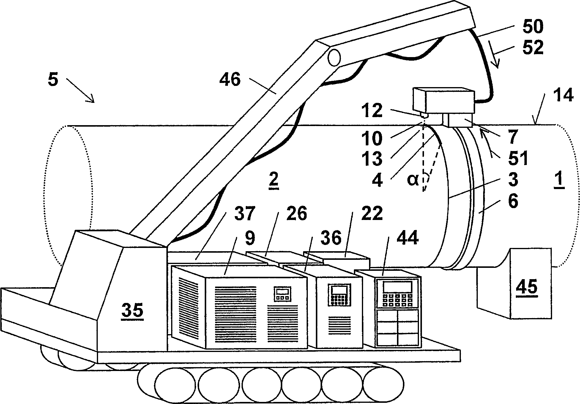
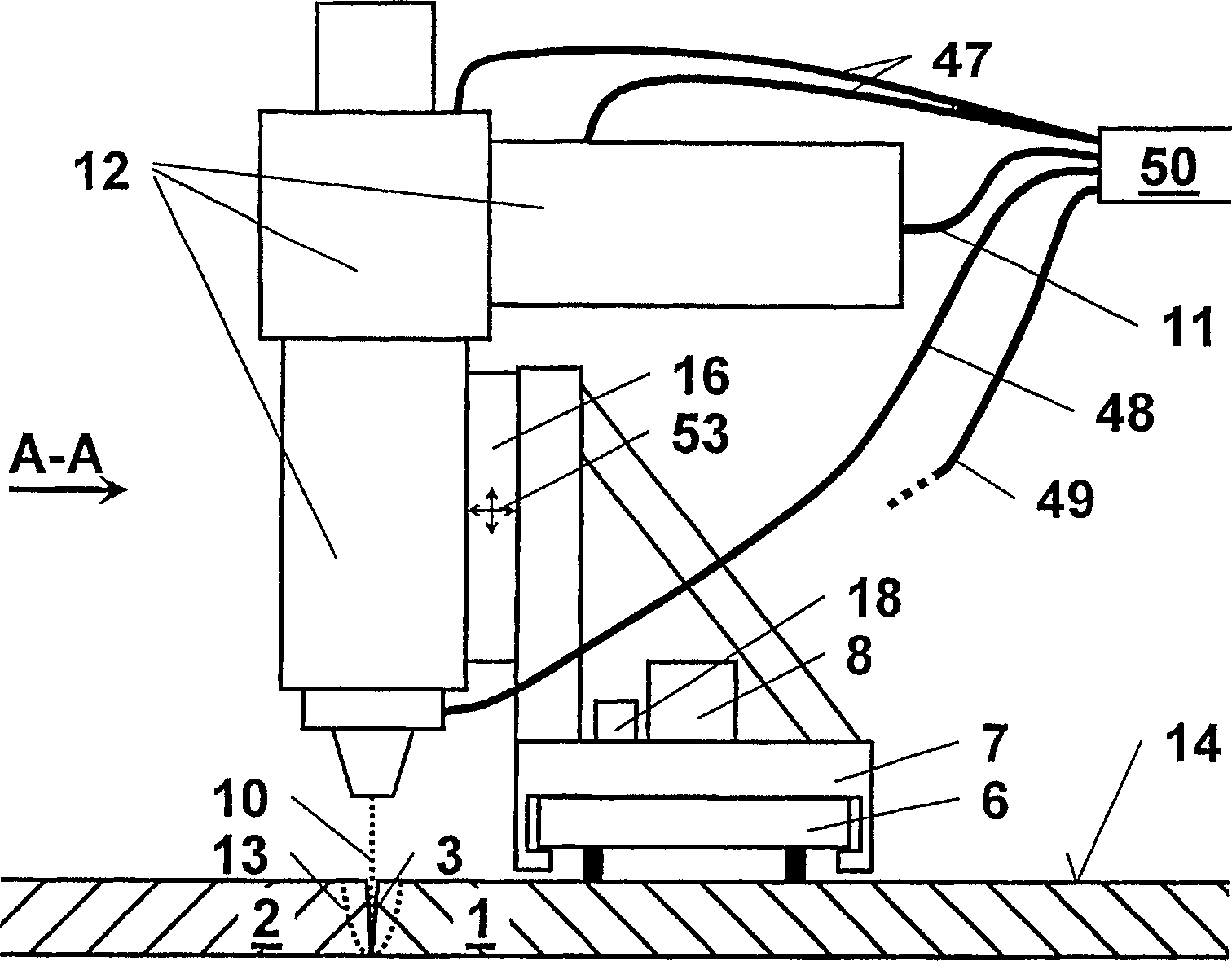
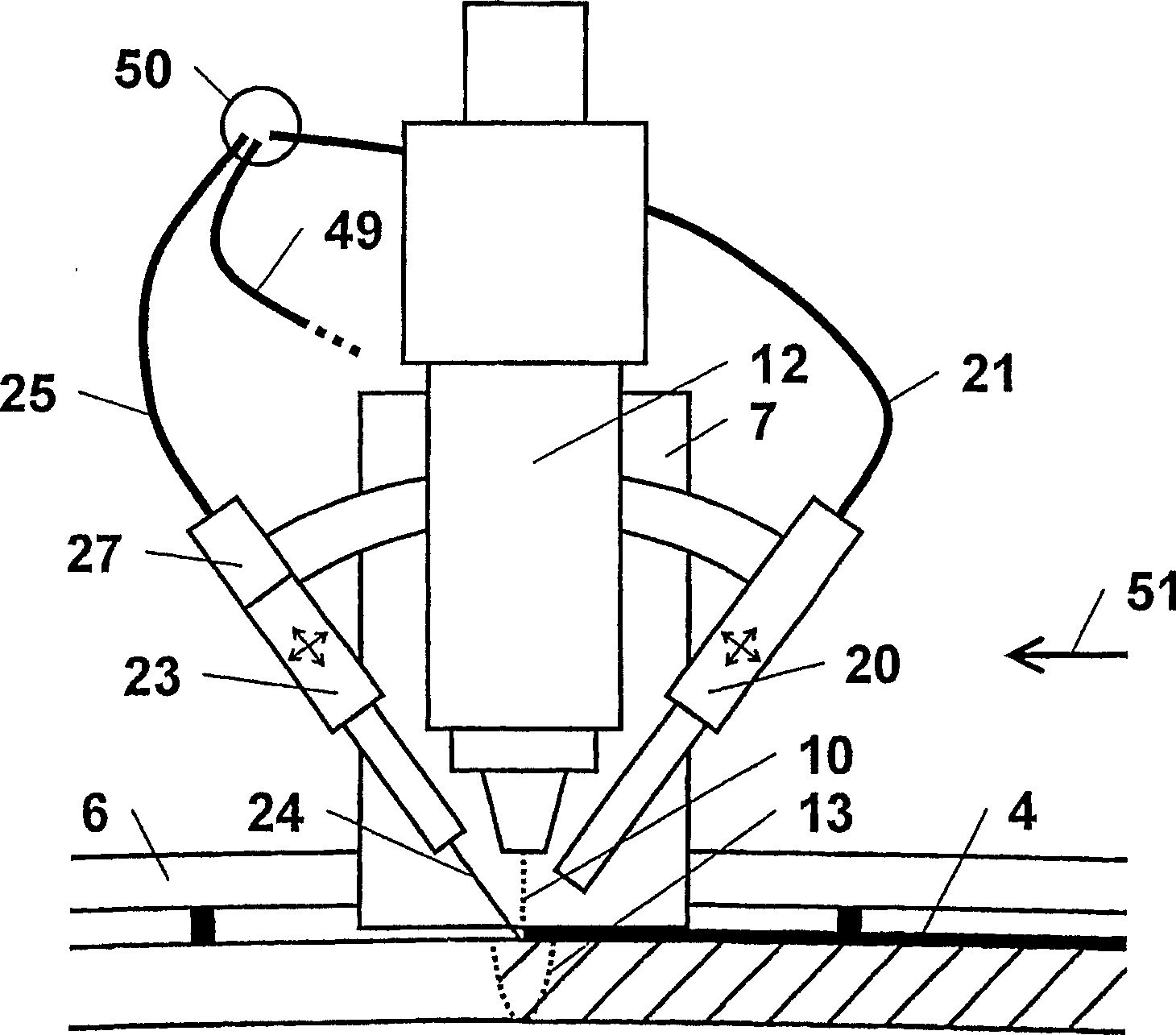
[0044] exist figure 1 , figure 2 and image 3 A first embodiment of the invention is shown in different views and with different degrees of detail. figure 1 The entire orbital welding device is shown as a three-dimensional schematic diagram of the pipeline erection site. The first pipe end 1 and the second pipe end 2 of the pipe 5 to be laid horizontally on the ground are aligned by means of known internal centering devices (not shown), at least one pipe crane (not shown) and pipe supports 45 and centered so that the circumferential joint 3 has a defined gap width of less than 0.3 mm between the first pipe end 1 and the second pipe end 2 and there is no edge misalignment. A guide ring 6 in the form of a retaining band with guide rails is arranged on the first pipe end 1 parallel to the circumferential joint 3 and at a fixed distance from the outer surface 14 of the first pipe end 1 . A rail bracket 7 is arranged on the guide ring 6 , which is movably guided along the guid...


PUM

PropertyMeasurementUnit
diameteraaaaaaaaaa
diameteraaaaaaaaaa
thicknessaaaaaaaaaa

Abstract

The invention relates to an orbital welding device for mobile use in order to join a first pipe ( 1 ) and a second pipe end ( 2 ) along a circumferential joint ( 3 ) by at least one weld seam ( 4 ), particularly for producing a pipeline ( 5 ) to be placed on land. The inventive device includes a guide ring ( 6 ), which can be oriented toward the first pipe end ( 1 ) and the circumferential joint ( 3 ), and an orbital carriage ( 7 ) that can be motor-displaced along the guide ring ( 6 ) via an advancing device ( 8 ). On the orbital carriage ( 7 ), a laser welding head ( 12 ) for directing a laser beam ( 10 ) into a laser welding zone ( 13 ) is mounted in a manner that enables it to be oriented toward the circumferential joint ( 3 ) whereby enabling the production of the weld seam ( 4 ) along the circumferential joint ( 3 ) by displacing the orbital carriage ( 7 ). The laser beam ( 10 ) is produced by a high-power fiber laser beam source ( 9 ) located, in particular, on a mobile transport vehicle ( 35 ) while being situated at a distance from the orbital carriage ( 7 ), is guided by light guide ( 11 ) passing through a tube bundle ( 50 ) to the orbital carriage ( 7 ) and then supplied to the welding head ( 12 ). A significant advantage of the invention resides in the fact that the joining of two pipe ends by only one single welding process during a short period of time is made possible in the field with autonomous operation.

Description

technical field [0001] The invention relates to an orbital welding device for joining pipelines by a circumferential weld, in particular for orbital welding of pipelines during mobile use. Background technique [0002] Devices for welding pipes circumferentially have been known for a long time, such devices are known as orbital welding devices. In diameters ranging from 50mm to over 1500mm and in wall thicknesses ranging from 2.5mm to over 25mm, the moving orbital welding method has largely replaced the previously used sleeve and thread joining techniques. Although most industrial welding cells operate in a stationary state in industrial workshops isolated from external influences, or at least perform welding operations on stationary products, however, in the case of line erection sites (for example, for pipe erection) , the production unit moves along the product to be finished, thus being exposed to the full influence of environmental changes and all kinds of weather. Of...

Claims


Application Information

Patent Timeline
Patent Type & Authority Applications(China)
IPC IPC(8): B23K26/08B23K26/10B23K26/14
CPCB23K26/1423B23K26/285B23K26/1429B23K26/045B23K26/04B23K26/103B23K26/044B23K26/282B23K26/348B23K37/0294
Inventor 埃吉哈德·沃纳·菲茨弗兰克·福勒特森哈拉尔德·科恩克劳斯·汤米
Owner FITS GMBKH
Why Eureka
Try Eureka