Cutter head for a trimmer

A technology of cutters and cutter heads, which is applied in the direction of cutters, harvesters, agricultural machinery and implements, etc.

Inactive Publication Date: 2007-01-10
ANDREAS STIHL AG & CO KG
View PDF1 Cites 2 Cited by
  • Summary
  • Abstract
  • Description
  • Claims
  • Application Information

AI Technical Summary

Problems solved by technology

The locking elements of the form-fit connection achieved by melting are subjected to high loads which can lead to pulling in of the head support

Method used


Image

  • Cutter head for a trimmer
  • Cutter head for a trimmer
  • Cutter head for a trimmer

Examples


Embodiment Construction

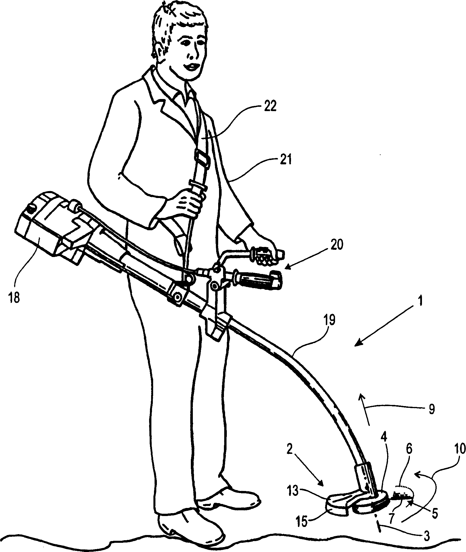
[0022] figure 1 Represent an operator 21 with a shoulder strap 22 to suspend a removal cutter 1 in a general working posture or an appearance diagram of an operating posture. The debriding cutter 1 comprises a conduit 19, at one end of which a motor unit 18 is arranged and at its opposite end a cutting head 4 is arranged. Inside the guide tube 19 there is a drive shaft, not shown, by means of which a drive motor, also not shown, drives the cutting head 4 in rotation. For actuating the clearing cutter 1 , a handle unit 20 is provided on the catheter 19 , on which the operating elements for controlling the drive motor are arranged.

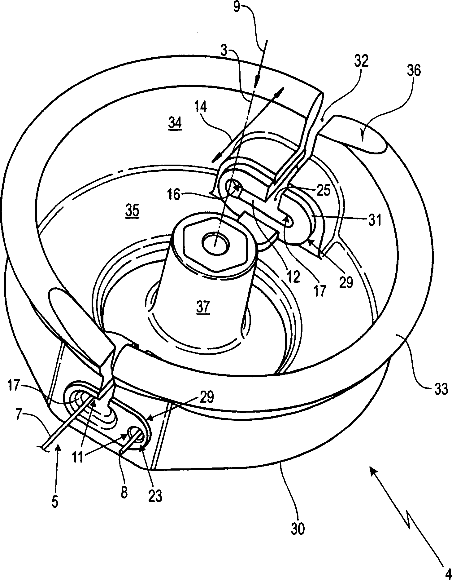
[0023] The cutter head 4 carries a cutting wire 5 which, during operation, rotates together with the cutter head 4 about a rotational axis 3 in the direction of rotation indicated by the arrow 10 . The flexible cutting wire 5 made of plastic is aligned approximately radially with the axis of rotation 3 due to the centrifugal force generated during...


PUM


Abstract

The invention relates to a cutting head (4) of a cleaning cutter (1), which is driven in rotation about an axis of rotation (3) and carries at least one cutting wire (5). The cutting wire (5) has a radially outer cutting zone (7) with respect to the axis of rotation (3) and is fixed on the cutting head ( 4) on. In order to fix the clamping end (8), a roughly U-shaped receiving groove (11) is provided on the cutter head (4). The clamping end (8) of the cutting wire (5) passes through the first side leg (16) of the U-shaped receiving groove (11), while the cutting zone (7) passes through the second side leg of the U-shaped receiving groove (11) (17). The receiving groove (11) between the two side legs (16, 17) is a clamping zone (38) for the cutting wire (5) with a wedge-shaped clamping tapered in the direction of the clamping end (8). Paragraph (12).

Description

technical field [0001] The invention relates to a cutting head of a clearing cutter, which is driven in rotation about an axis of rotation and carries at least one cutting wire, wherein the cutting wire has a radially outer cutting zone with respect to the axis of rotation, and The inner portion of the clamping end adjoining the cutting zone is fixed to the cutter head. Background technique [0002] Motorized sickles or clearing cutters of known design have a drive motor, for example in the form of an internal combustion engine, which drives a cutting head in rotation about an axis of rotation by means of a shaft mounted in a guide tube. The cutting head carries a cutting wire which, when the cutting head is rotated in the direction of rotation, rotates and is substantially radially aligned with the axis of rotation due to the centrifugal force generated. During its rotational movement, the cutting wire defines a cutting circle. A protective hood is arranged in the region ...

Claims


Application Information

Patent Timeline
Patent Type & Authority Applications(China)
IPC IPC(8): A01D34/73
CPCA01D34/902A01D34/416A01D34/4166
Inventor D·昂斯滕贝尔格
Owner ANDREAS STIHL AG & CO KG
Why Eureka
Try Eureka