Stacker crane

A lift and stacking technology, applied in the field of stacking lifts, can solve the problems of increased vibration and increased mast dust, and achieve the effects of reducing load, suppressing vibration and dust, and suppressing vibration

Inactive Publication Date: 2007-01-10
DAIFUKU CO LTD
View PDF0 Cites 10 Cited by
  • Summary
  • Abstract
  • Description
  • Claims
  • Application Information

AI Technical Summary

Problems solved by technology

[0004] In order to suppress the vibration of the upper part of the mast, if the upper part of the mast is driven like a driving device for driving the lower part, the vibration can be suppressed, but if the driving force of the upper part is increased, the vibration will increase due to the weight of the mechanical parts required for its driving. , the increase of the driving force will also increase the dust generated on the upper part of the mast

Method used


Image

  • Stacker crane
  • Stacker crane
  • Stacker crane

Examples


Embodiment 1

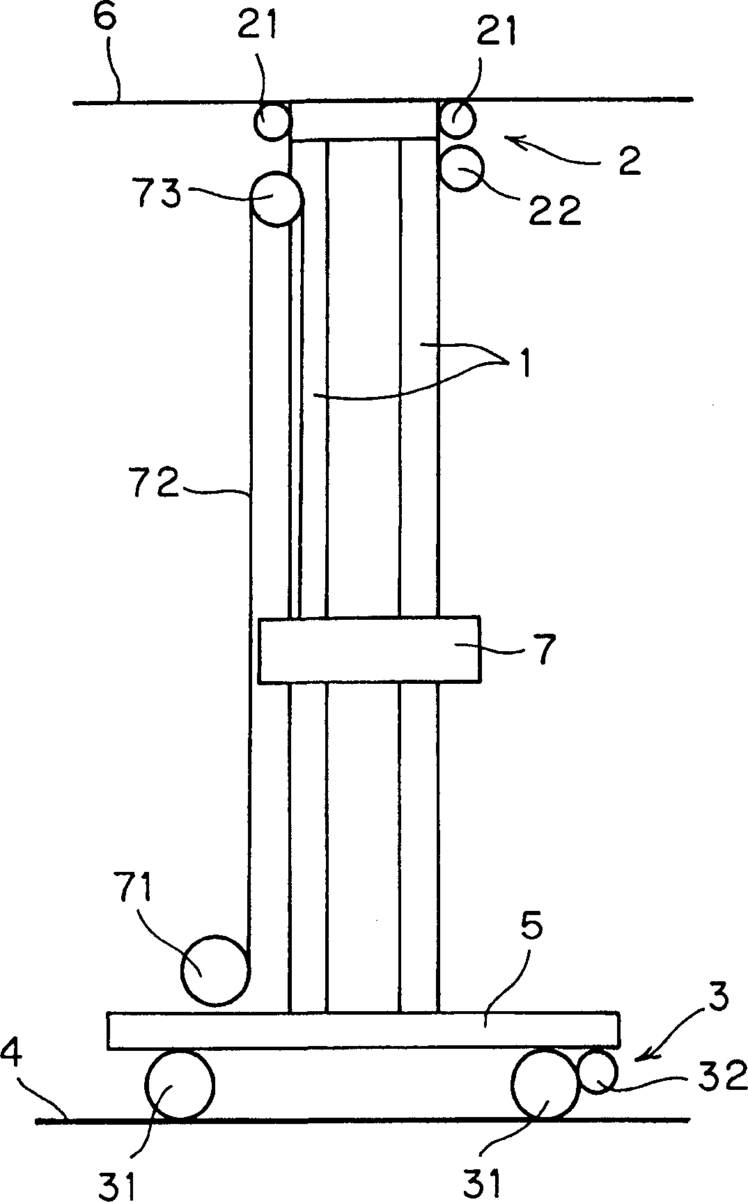
[0031] figure 1 An embodiment of the stacker elevator of the invention is shown.

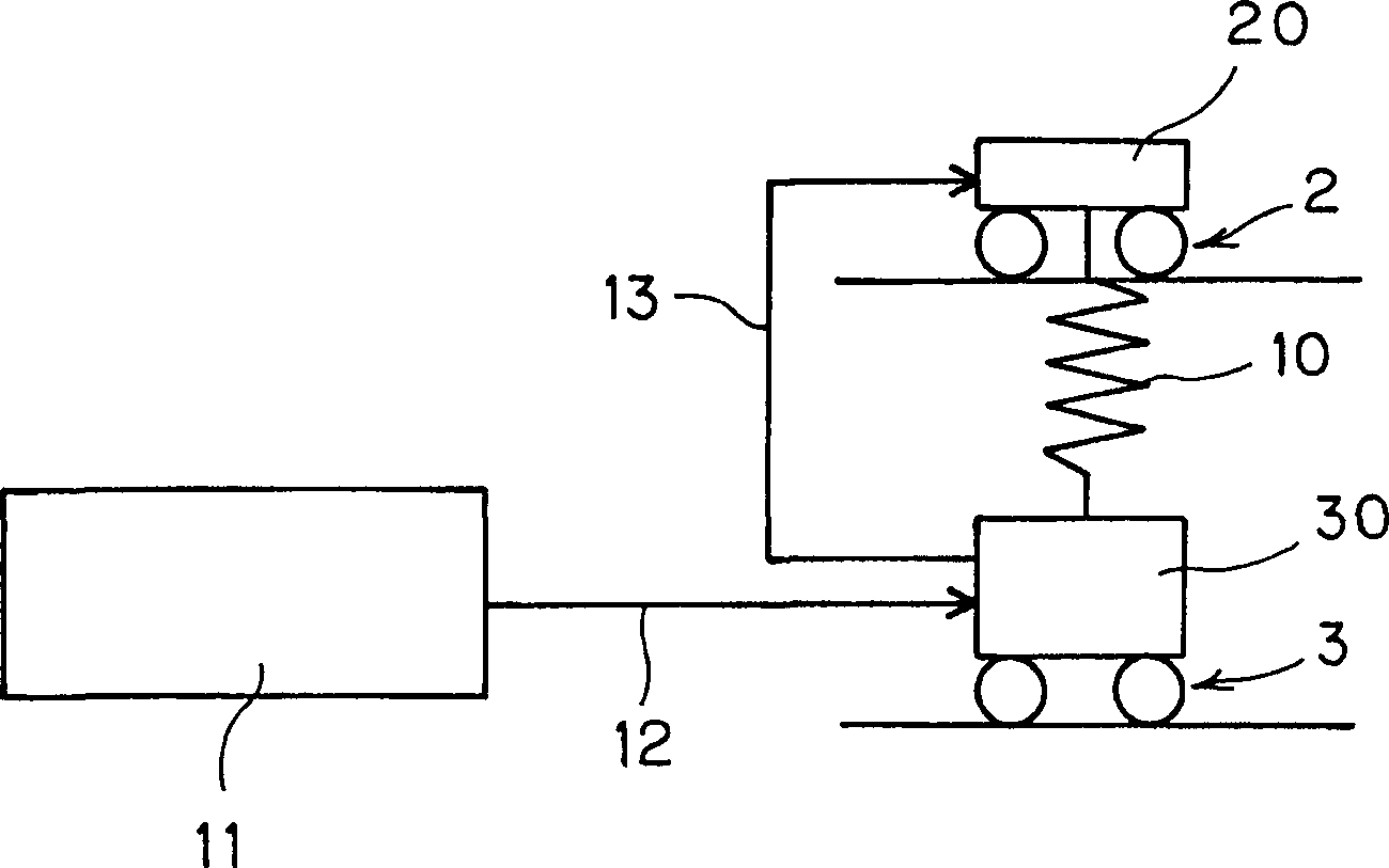
[0032] The stacker elevator of the present embodiment is respectively provided with an upper travel drive device 2 and a lower travel drive device 3 at the top and bottom of the mast 1 of the stacker lifter. While using the lower travel drive device 3 to implement the travel and position control of the stacker elevator, the upper travel drive device 2 is driven according to the speed signal of the lower travel drive device 3, and the vibration of the mast 1 is suppressed by the upper travel drive device 2 .

[0033] The lower driving device 3 includes lower driving wheels 31 running on the running rail 4 on the ground side and a lower driving motor 32 driving the lower driving wheels 31 on the traveling vehicle 5 .

[0034] In addition, the upper traveling driving device 2 is provided with an upper driving wheel 21 traveling along the support rail 6 on the ceiling side and an upper driving moto...


PUM


Abstract

The upper travelling driving device 2 and a lower travelling driving device 3 are provided in an upper part and a lower part of the mast 1 of the stacker crane. The lower travelling driving device 3 controls travelling and position of the stacker crane, and the upper travelling driving device 2 is driven on the basis of a speed signal of the lower travelling driving device 3 so as to restrict vibration of the mast 1 with the upper travelling driving device 2.

Description

technical field [0001] The present invention relates to a low-dust stacker elevator used in a clean room for storing wafer boxes and glass boxes related to liquid crystals and semiconductors, and more particularly to a stacker elevator capable of suppressing vibration at the upper part of a mast. Background technique [0002] When a stacker elevator is installed in an automatic warehouse installed in a clean room, since the storage and transportation are carried out from the ground to the ceiling, the moving distance in the up and down direction is relatively short, only a few meters, so it is usually only in the The lower part of the mast of the stacker lift is provided with a traveling driving device to make it move on the traveling track. [0003] In the case of connecting multi-storey warehouses and extending the lifting and moving range of the stacking elevator to an automatic warehouse with more than 2 floors, if only a driving device is installed on the lower part of ...

Claims


Application Information

Patent Timeline
Patent Type & Authority Applications(China)
IPC IPC(8): B65G49/00B65G1/04B65G57/00
CPCB65G1/0421B66F9/072H02P23/22
Inventor 山本治正珍部弘远藤嘉也水泽和浩
Owner DAIFUKU CO LTD
Why Eureka
Try Eureka