Sputtering equipment

A sputtering device and substrate technology, applied in sputtering coating, vacuum evaporation coating, coating, etc., can solve problems such as uneven material composition

Active Publication Date: 2007-01-10
LG DISPLAY CO LTD +2
View PDF1 Cites 2 Cited by
  • Summary
  • Abstract
  • Description
  • Claims
  • Application Information

AI Technical Summary

Problems solved by technology

[0016] Also, when the substrate is large, the composition of the material deposited on the substrate is not uniform

Method used


Image

  • Sputtering equipment
  • Sputtering equipment
  • Sputtering equipment

Examples


Embodiment Construction

[0031] Reference will now be made in detail to the preferred embodiments of the invention, examples of which are illustrated in the accompanying drawings. However, this invention may be embodied in different forms and should not be construed as limited to the embodiments provided herein; rather, these embodiments are provided so that this disclosure will be thorough and complete, and to convey to those skilled in the art Convey the principles of the invention.

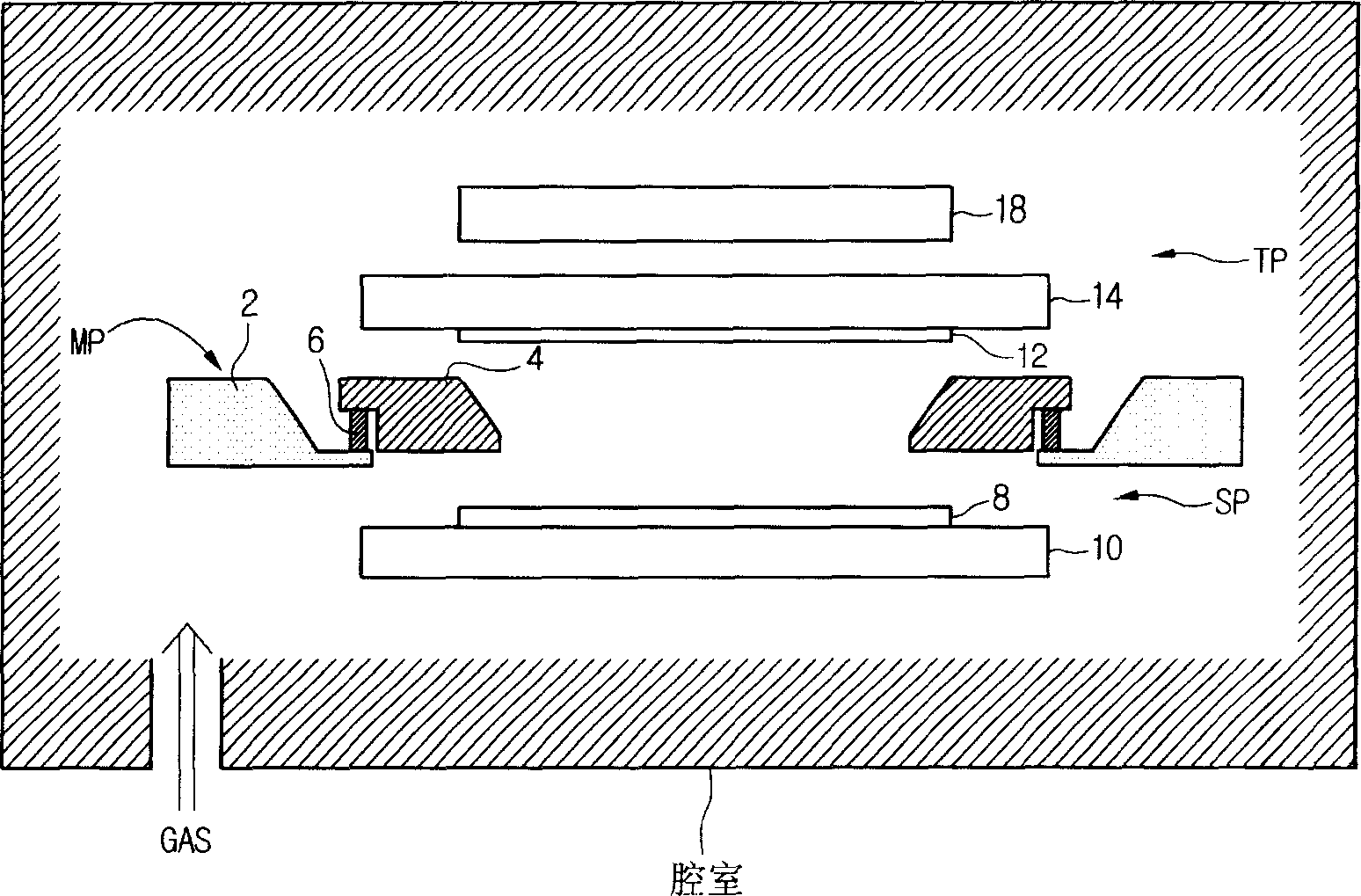
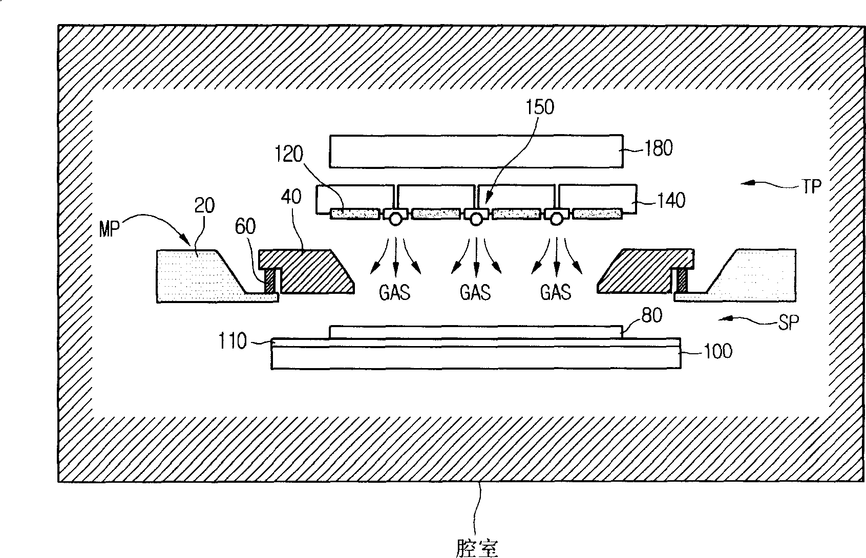
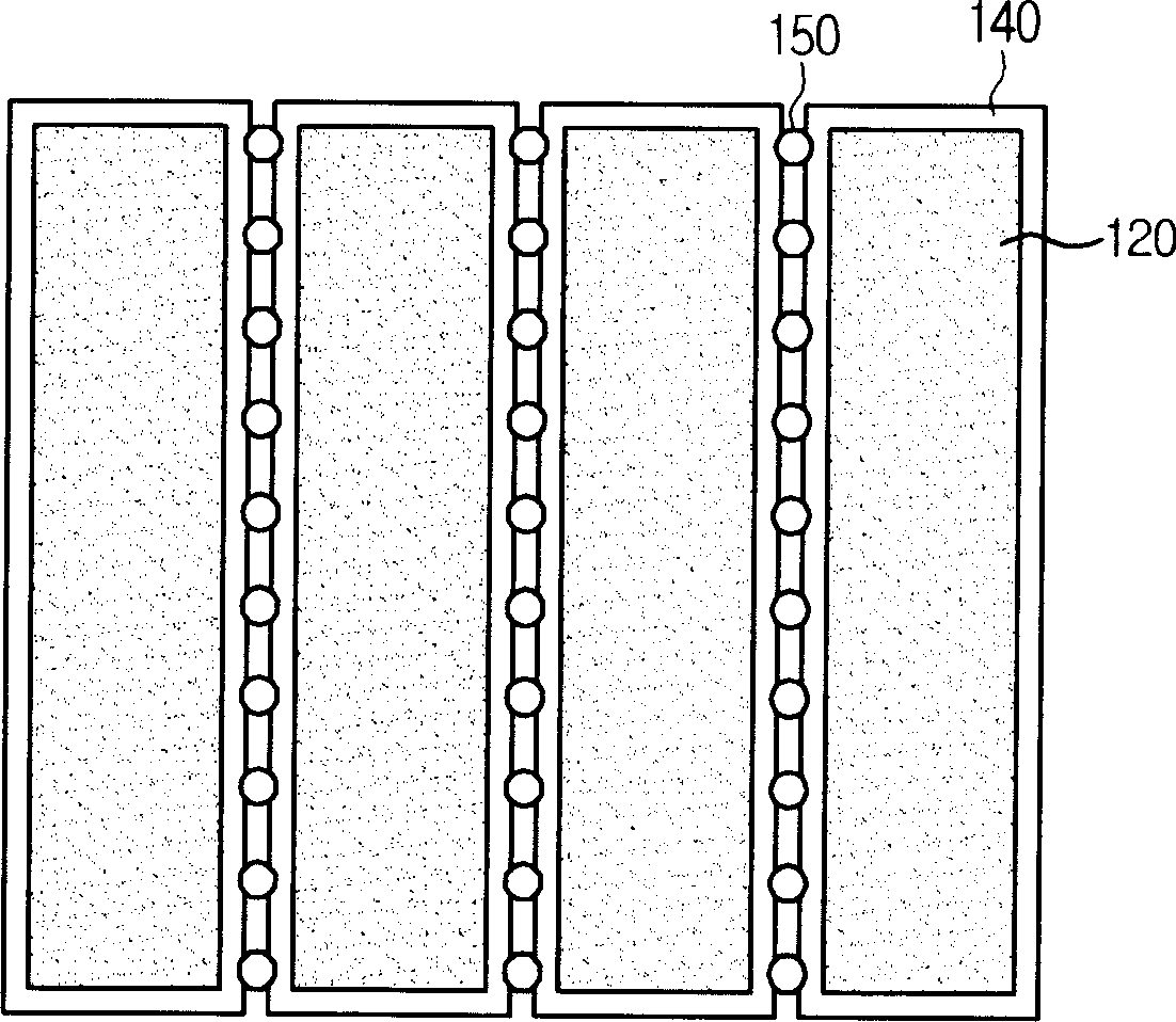
[0032] According to a feature of the invention, the target is divided into target areas and said target areas are attached to the cathode plate. A plurality of gas supply ports are provided in the area between the target areas.

[0033] An inert gas is supplied into the chamber through the plurality of gas supply ports to be evenly distributed to a space between the cathode plate and the anode plate disposed in the chamber, thereby improving the properties of the thin film to be deposited on the substrate. Uniformity...


PUM


Abstract

The present invention provides a sputtering device, comprising: a substrate unit, which includes a substrate located in a cavity, on which a target is deposited; a target unit, which has a plurality of target areas formed by the target and is used for A cathode plate for supplying electrical energy to the surface of the target volume; a plurality of gas supply ports provided on the area between the target volumes.

Description

technical field [0001] The present invention relates to a sputtering device, and more particularly, to a sputtering device having a plurality of gas ports provided on a cathode plate between target regions formed on the cathode plate. Background technique [0002] Generally, a sputtering apparatus is used to deposit a target material on a substrate by accelerating ions using plasma and allowing the ions to collide with a target formed of a target material. [0003] The sputtering process using a sputtering device has the ability to form a thin film at a relatively low temperature of about 400° C. compared to chemical deposition performed at a relatively high temperature. [0004] The sputtering device includes a target unit and a substrate unit arranged in a chamber. The target unit and the substrate unit are respectively connected with the cathode and the anode. When a DC power is applied to the cathode and a high frequency is generated at the anode, electrons are emitted...

Claims


Application Information

Patent Timeline
Patent Type & Authority Applications(China)
IPC IPC(8): C23C14/34C23C14/54
CPCH01J37/3244H01J37/34C23C14/3464C23C14/34C23C14/3407C23C14/54
Inventor 金成垠李千洙刘桓圭尹炳汉
Owner LG DISPLAY CO LTD
Why Eureka
Try Eureka