

Continuously blockable adjustment device
An adjusting device and locking technology, which are applied in the directions of the shutter of the wing leaf, the fastening device of the wing leaf, the control mechanism of the wing leaf, etc.
- Summary
- Abstract
- Description
- Claims
- Application Information
AI Technical Summary
Problems solved by technology
Method used
Image

Examples
Embodiment Construction
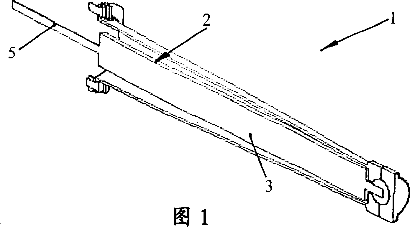
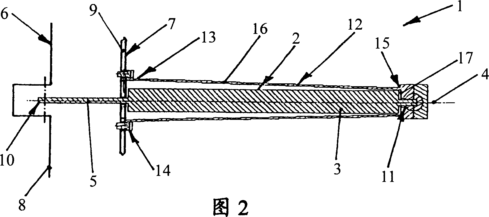
[0032] FIG. 1 shows an infinitely lockable adjusting device 1 with a piston-cylinder unit 2 with a cylinder 3 and can be positioned in the axial direction of the cylinder 3 , that is to say on the center axis of the piston-cylinder unit 2 . 4 direction (as shown in Figure 2) moving piston, the piston has a piston rod 5 stretched out from the cylinder. The adjusting device serves to position the two relatively movable parts 6, 7 (as shown in FIG. 2). In the present exemplary embodiment, the first part 6 of the relatively movable parts 6 , 7 is here the motor vehicle body 8 , which is only partially shown, and the second part 7 is the motor vehicle door 9 , which is also only partially shown. . The vehicle door 9 is pivotable relative to the vehicle body 8 about a not shown pivot axis.
[0033]The piston-cylinder unit 2 has a piston-rod-side connecting piece 10 for connecting to the vehicle body 8 and has a cylinder-side connecting piece 11 for connecting to the vehicle door 9...
PUM
 Abstract
Description
Claims
Application Information