Dual piezoelectric beam driven diaphram air pump

A dual piezoelectric and diaphragm technology, which is applied to pumps with flexible working elements, pumps, components of pumping devices for elastic fluids, etc., can solve problems such as difficulty in meeting chip heat dissipation requirements, and achieve low power consumption. , The effect of large output flow and small side size

Inactive Publication Date: 2007-01-10
TSINGHUA UNIV +1
View PDF0 Cites 17 Cited by
  • Summary
  • Abstract
  • Description
  • Claims
  • Application Information

AI Technical Summary

Problems solved by technology

Therefore, traditional heat dissipation methods such as installing fans and e...

Method used


Image

  • Dual piezoelectric beam driven diaphram air pump
  • Dual piezoelectric beam driven diaphram air pump
  • Dual piezoelectric beam driven diaphram air pump

Examples


Embodiment 2

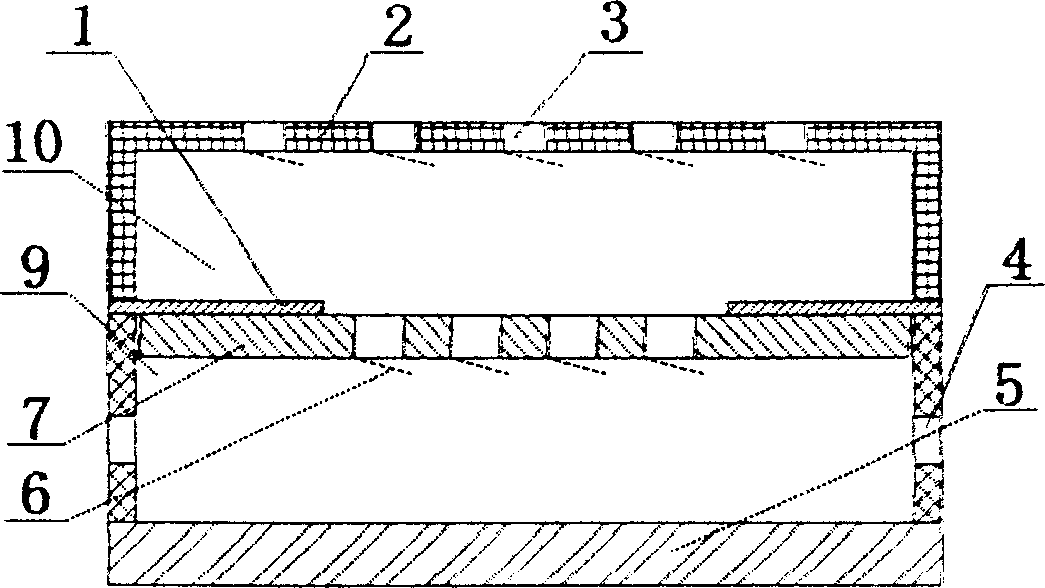
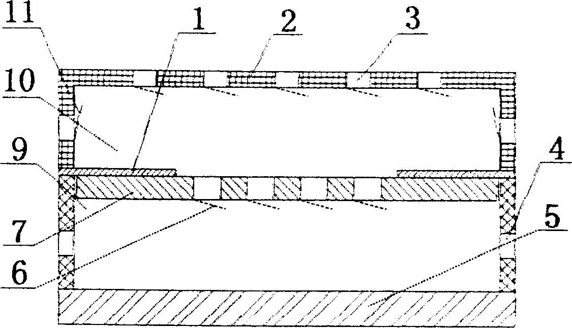
[0015] The difference between this embodiment and the previous embodiment is that a check valve 11 is added on the side of the upper chamber 10 (such as image 3 ). The advantage of this is that on the one hand, the flow rate of the upper chamber of the diaphragm air pump can be increased; on the other hand, when the one-way valve hole at the top of the upper chamber is blocked, the upper chamber can still be exchanged through the side check valve 11. gas. The structure, manufacturing and assembly methods of other parts of this embodiment are exactly the same as those of Embodiment 1, but the movement of the diaphragm should not interfere with the work of the one-way valve 11 during the manufacturing process.

Embodiment 3

[0017] The difference between this embodiment and the first embodiment is that the holes 4 on the side walls of the upper chamber 10 and the lower chamber 9 and the one-way valve 11 on the side of the upper chamber 10 can also be trapezoidal holes / trapezoidal valves. This kind of valve realizes the one-way flow of air flow by utilizing the different flow resistances in the two directions of the trapezoidal hole / trapezoidal valve. Its manufacturing process is simpler than that of the one-way valve with the valve plate, thus greatly increasing the reliability of the diaphragm air pump. sex.


PUM


Abstract

The invention discloses a double-piezoelectric beam driven diaphragm pump, belonging to the technical field of micro fluid pump in precision machinery, comprising a cavity, two double-piezoelectric beams, a diaphragm with one-way valve and electrodes, where one end of each double- piezoelectric beam is fixedly supported and the other end is connected with the side of the diaphragm, an AC voltage is applied on the double- piezoelectric beams in the cavity to drive the diaphragm to vibrate at resonance point, and under the action of the one-way valve on the diaphragm, the air flows in a direction to exchange with external gas. And it has many advantages of simple structure, large output flow, low power consumption, small size of side surface, no electromagnetic noise, fewer active parts, high reliability, etc, easy to spread and apply.

Description

technical field [0001] The invention belongs to the technical field of micro fluid pumps in precision machinery, in particular to a diaphragm air pump driven by double piezoelectric beams. Background technique [0002] For more than 30 years, the rapid improvement of chip performance has led to the vigorous development of a new economy dominated by information technology. However, with the improvement of transistor integration, the problems of chip energy consumption and heat dissipation have gradually become prominent. Therefore, the cooling of microelectronic devices has become a research hotspot in the international microelectronics field. However, with the miniaturization of electronic equipment such as computers, the cooling device for its internal chip should have the characteristics of low power consumption, low noise, small side size and volume, high efficiency, and high reliability. Therefore, traditional heat dissipation methods such as installing fans and extern...

Claims


Application Information

Patent Timeline
IPC IPC(8): F04B45/047F04B45/04F04B43/02
CPCF04B45/045F04B45/047F04B53/10F04B53/16F05B2210/12F16K15/00
Inventor 周兆英杨兴叶雄英赵慧贞罗小兵
Owner TSINGHUA UNIV
Why Eureka
Try Eureka