Zooming-projection camera lens

A projection lens and projection display technology, applied in the field of zoom projection lenses, can solve the problems of design conditions and parameter values ​​without any description, and achieve the effects of improving projection quality, compact structure, and aberration correction

Inactive Publication Date: 2007-01-10
ASIA OPTICAL CO INC
View PDF2 Cites 6 Cited by
  • Summary
  • Abstract
  • Description
  • Claims
  • Application Information

AI Technical Summary

Problems solved by technology

However, this patent only gives a general introduction to the structure and function of the projection lens, but does not make any explanation on the specific design conditions and parameter values, so further research is needed to solve the aberration problem that still exists

Method used


Image

  • Zooming-projection camera lens
  • Zooming-projection camera lens
  • Zooming-projection camera lens

Examples


Embodiment Construction

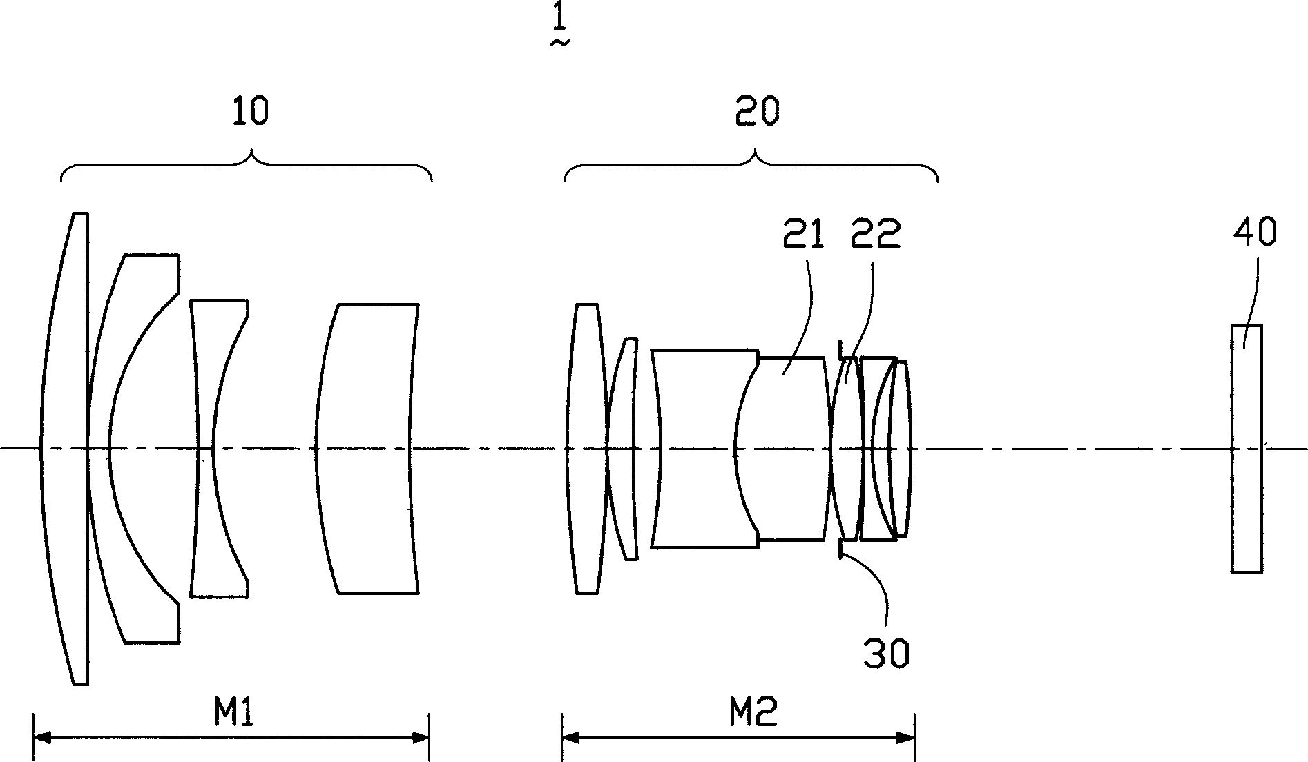
[0038] Please refer to figure 1 As shown, the zoom projection lens 1 of the present invention can be installed on a DLP projector to project the image on the DMD imager onto the screen. The zoom projection lens 1 includes a first lens group 10 with negative diopter and a lens group with positive diopter The second lens group 20, wherein the first lens group 10 is made up of several lenses, which are installed on the screen side (such as figure 1 shown in the left side) and can move along the optical axis in the range of the first variable distance M1, the so-called screen side refers to a plane on which the image can be projected; the second lens group 20 is composed of several lenses composition, which is mounted on the image plane side (eg figure 1 The right side shown in ) and can move along the optical axis within the range of the second variable pitch M2, the so-called image plane side refers to the installation position of the DMD imager (not shown). Another aperture s...


PUM


Abstract

The present invention discloses zooming projection lens capable of installing in projection display device. Zooming projector lens includes first lens assembly having negative dioptre and second lens assembly having positive dioptre, wherein first lens assembly consisting of plurality of lens near by image surface and capable of moving along optical axis, second lens assembly consisting of plurality of lens near by object plane and capable of moving along optical axis, one aperture stop set between two adjacent lens of second lens assembly, said aperture stop capable of moving along with second lens assembly, said zooming projector lens capable of correcting aberration, thereby raising projection quality.

Description

【Technical field】 [0001] The invention relates to a zoom projection lens, in particular to a zoom projection lens applicable to the projection display optical system of a projection device and the image capture optical system of an image capture device. 【Background technique】 [0002] Projectors can be divided into CRT (Cathode Ray Tube) projectors, LCD (Liquid Crystal Display) projectors, DLP (Digital Light Processing) projectors and LCoS (Liquid Crystalon Silicon) projectors, all of which use optical projection , to project the image on a large screen. For example, a DLP projector uses a DMD (Digital Micromirror Device) as a light valve imager. The imaging principle is to control the reflection direction of light by the rotation of the DMD micromirror device (±10°), so that the on-off of the signal at this point can be controlled. , and then project the image on the DMD micromirror device onto the screen through an optical lens. [0003] The quality of the picture projec...

Claims


Application Information

Patent Timeline
Patent Type & Authority Applications(China)
IPC IPC(8): G02B9/10G02B7/02G02B15/14
Inventor 郭仲渊
Owner ASIA OPTICAL CO INC
Why Eureka
Try Eureka