Motor driven slide variable resistor

A motor drive and resistor technology, applied in the direction of the resistance element adjusted by the auxiliary drive device, can solve the problems of the quality level of the lossy device, the change of the moving speed of the motor drive, etc., achieve the effect of high quality level and reduce deviation

Active Publication Date: 2007-01-10
ALPS ALPINE CO LTD
View PDF1 Cites 7 Cited by
  • Summary
  • Abstract
  • Description
  • Claims
  • Application Information

AI Technical Summary

Problems solved by technology

[0014] However, in the structure of the conventional motor-driven sliding type varistor, since the driven pulley rotates through the rivet, the rivet also rotates a little during use, and the mounting position of the rivet changes. As a result, the tension (tension condition) of the belt that has been adjusted changes, so there is a problem that the moving speed changes when the motor is driven.
[0015] In addition, in the case of using a plurality of them in parallel, if there is a large difference in the respective moving speeds, there is a problem that the quality level of the device (set) will be impaired.

Method used


Image

  • Motor driven slide variable resistor
  • Motor driven slide variable resistor
  • Motor driven slide variable resistor

Examples


Embodiment Construction

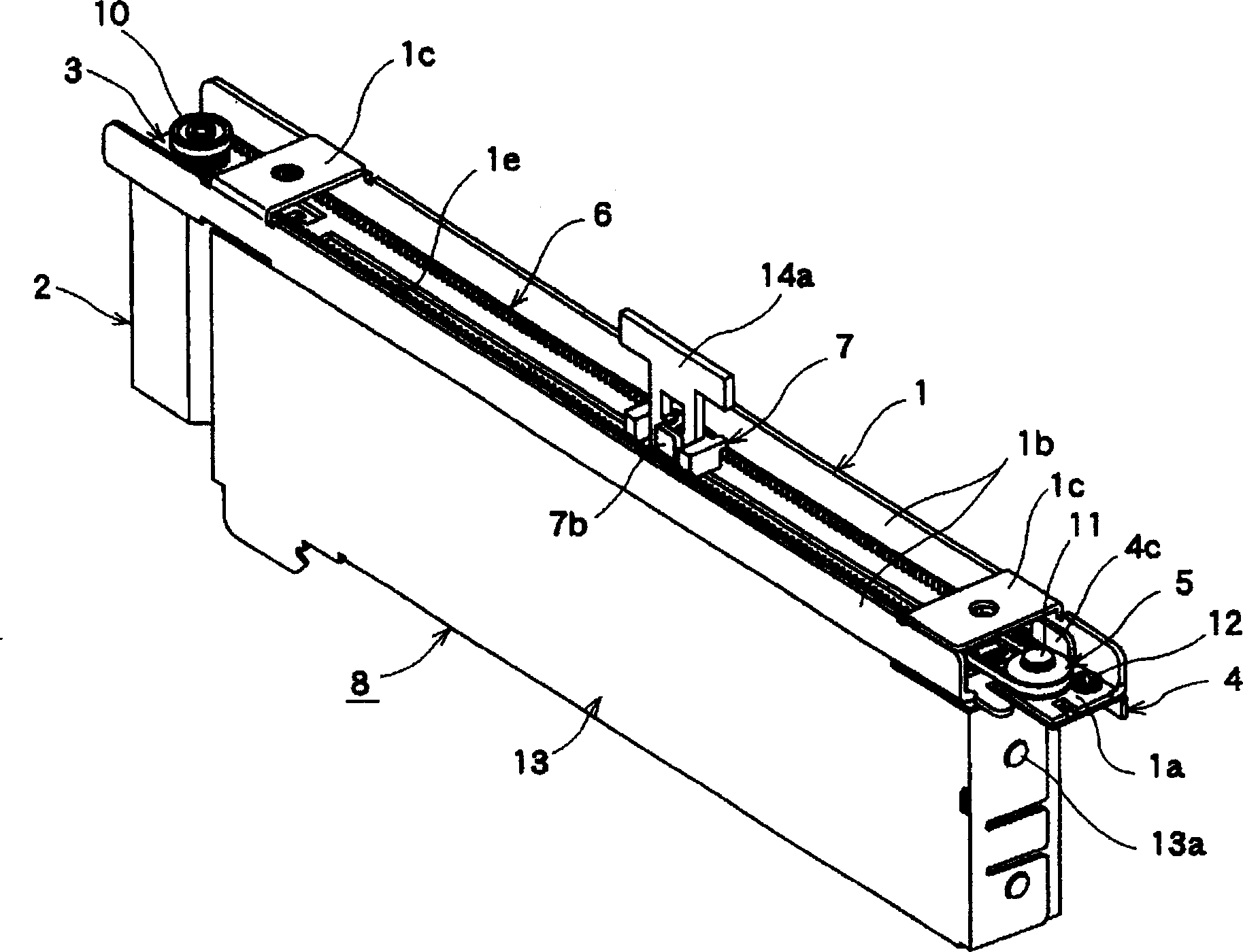
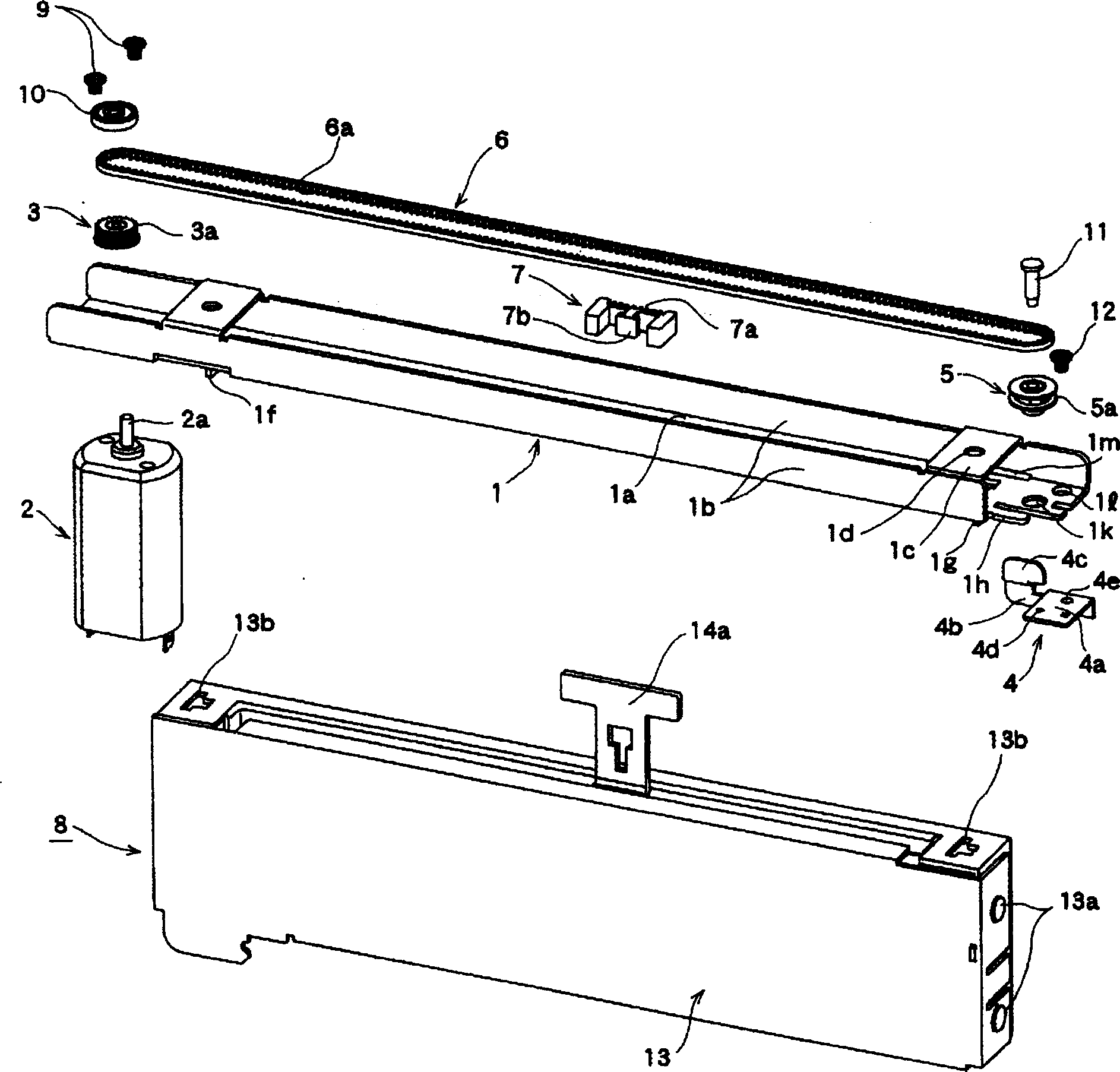
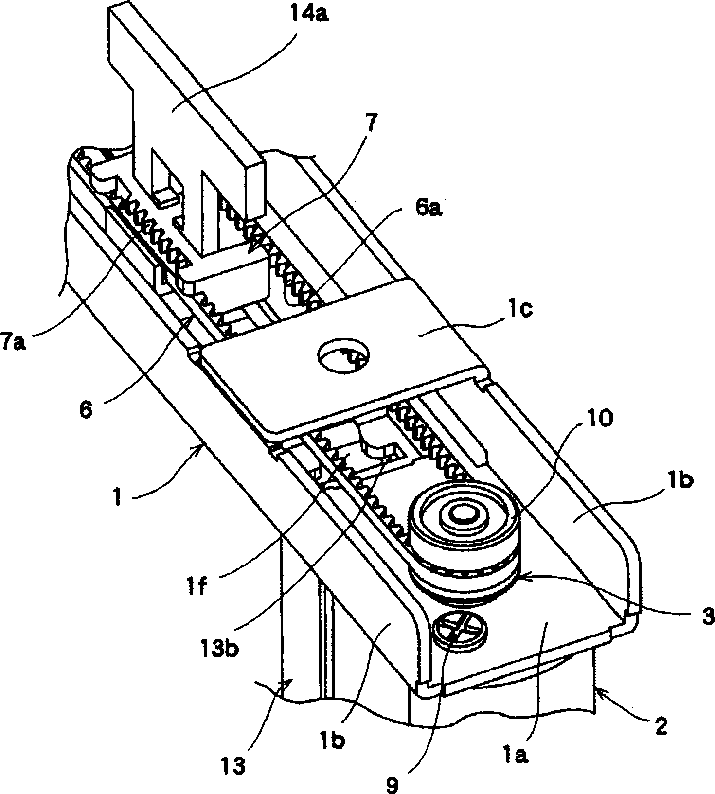
[0044] Below, the embodiments of the present invention are as Figure 1 to Figure 1 0 shown. figure 1 Is a perspective view showing the motor-driven sliding variable resistor of the present invention, figure 2 Is an exploded perspective view showing the motor-driven sliding variable resistor of the present invention, image 3 Is an enlarged perspective view of the motor side of the motor-driven sliding variable resistor of the present invention, Figure 4 It is an enlarged exploded perspective view of the motor side of the motor-driven sliding variable resistor of the present invention, Figure 5 It is an enlarged perspective view of the driven pulley side of the motor-driven sliding variable resistor of the present invention, Figure 6 It is an enlarged exploded perspective view of the driven pulley side of the motor-driven sliding variable resistor of the present invention, Figure 7 It is an explanatory diagram of the moving body and the variable resistor part moved to the mot...


PUM


Abstract

To provide a motor-driven sliding variable resistor having reduced in variation in working speed when a motor is driven and in the sense of operation when it is manually operated, and capable of maintaining performance for a long period of time. The resistor is provided with a frame 1 having a motor 2 attached on its one end; a driving pulley 3 coupled to a rotary shaft 2a of the motor; a driven pulley 5 arranged on the other end of the frame; a circular belt 6 stainedly hung over between the driving pulley and the driven pulley; and a variable resistor 8 attached to the frame so that a resistance value is adjusted by the movement of a moving body 7 coupled to the belt in the longitudinal direction of the frame. A movable member 4 movable in the longitudinal direction of the frame is provided at the other end of the frame, a pillar 11 for pivotally supporting the driven pulley, an attaching portion 4e is formed on a position different from the position where the pillar is fixed to the movable member, and the movable member is attached to the frame at the attaching position.

Description

Technical field [0001] The present invention relates to a motor-driven sliding type variable resistor used in a mixer for audio equipment and the like. Background technique [0002] As the structure of the conventional motor-driven sliding type variable resistor, the following structure is known, which has: an elongated cross-sectional L-shaped frame; an operating lever is inserted through a straight line provided in the frame Sliding variable resistor with slits; a motor with a timing pulley mounted on the front end of the rotating shaft fixed to one end of the frame in the longitudinal direction; a driven belt rotatably mounted on the other end of the frame Wheels; and an endless timing belt spanned between these timing pulleys and driven pulleys, and whose middle portion is fixed to the operating lever (for example, refer to Patent Document 1). [0003] The structure of the existing motor-driven sliding variable resistor is shown in Figure 11 to Figure 13 Shown. [0004] Fig....

Claims


Application Information

Patent Timeline
Patent Type & Authority Applications(China)
IPC IPC(8): H01C10/14
Inventor 佐佐木勋司池之上忍笠岛正男
Owner ALPS ALPINE CO LTD
Why Eureka
Try Eureka