Crank gear for a reciprocating compressor

A crank drive and compressor technology, which is applied in the direction of machines/engines, mechanical equipment, liquid variable capacity machinery, etc., can solve problems such as inaccurate balance performance

Inactive Publication Date: 2007-01-10
诺沃皮尼奥内控股有限公司
View PDF0 Cites 8 Cited by
  • Summary
  • Abstract
  • Description
  • Claims
  • Application Information

AI Technical Summary

Problems solved by technology

[0015] This therefore leads to an imprecise balance of performance, since the performance of the rotating part of the connecting rod is approximately

Method used


Image

  • Crank gear for a reciprocating compressor

Examples


Embodiment Construction

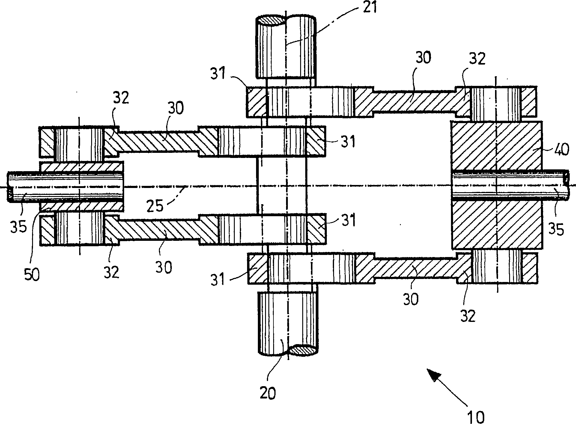
[0023] refer to figure 1 , which shows a crank gear 10 for a reciprocating compressor, on which a module can be applied comprising two working axes with two oppositely oriented cylinders? .

[0024] Said crank gear is adapted to constrain the two cylinders on the crank shaft 20 and keep them opposite each other with respect to the axis 21 of the shaft 20 .

[0025] The crank transmission 10 includes two rods 35 and a series of connecting rods 30, each connecting rod has its first end 31 connected to the shaft 20 and its second end 32 connected to one of the two rods 35. Each of the two rods 35 is respectively connected to one of the two cylinders.

[0026] The series of connecting rods 30 comprises identical connecting rods 30 arranged symmetrically with respect to the axis of alignment 25 of the two cylinders.

[0027] Furthermore, the connecting rods 30 of said series of connecting rods 30 are connected in pairs to two rods 35 by means of two crossheads 40 and 50 respecti...


PUM


Abstract

Crank gear (10) for a reciprocating compressor of the type equipped with at least one module which has two lines with two opposite cylinders. The crank gear is suitable for constraining the two cylinders to a crankshaft (20), so as to align the two cylinders, opposite each other with respect to an axis (21) of the shaft (20). The crank gear (10) is equipped with two rods (35), a series of connecting rods (30) and two cross heads (40) and (50). The series of identical connecting rods (30) is symmetrically positioned with respect to the alignment axis (25) of the two cylinders and furthermore the overall barycentre of the series of connecting rods lies on the axis (25) and on the axis (21) of the shaft (20) so that the whole of the shaft (20) is both statically and dynamically balanced.

Description

technical field [0001] The present invention relates to a crank gear for a reciprocating compressor, in particular a reciprocating compressor with opposing cylinders. Background technique [0002] When the reciprocating compressor works, dynamic forces are generated such as the centrifugal force of the rotating parts and the inertial force of the alternating working parts. [0003] Dynamic forces, and associated moments, can cause their foundations to be unstable, which in some applications can lead to excessive vibration and excessive stress. [0004] One way of attenuating the above-mentioned disadvantages is to balance the rotating parts and the parts constrained to the crank shaft to work alternately in two oppositely directed axes. [0005] Generally, the above-mentioned effect is obtained by arranging a counterweight integrally with the crank shaft. [0006] The crank gear comprises two oppositely oriented cylinders, each of which is arranged on an axis. [0007] Ea...

Claims


Application Information

Patent Timeline
Patent Type & Authority Applications(China)
IPC IPC(8): F04B27/02F04B39/00F02B75/24F02B75/06
CPCF02B75/24F04B27/02Y10T74/18184F02B75/065F04B39/0022
Inventor N·坎波S·普拉特西F·格拉兹亚尼
Owner 诺沃皮尼奥内控股有限公司
Why Eureka
Try Eureka